ENP Nickel Plating

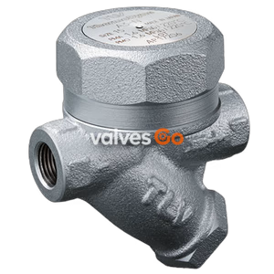
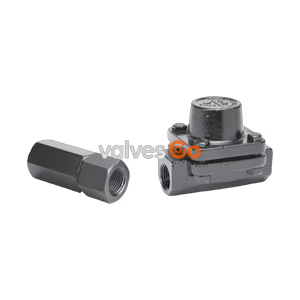
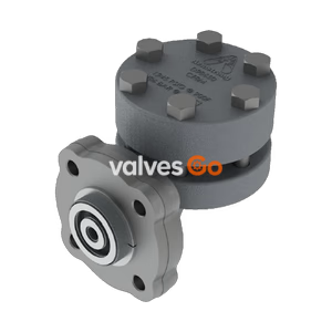
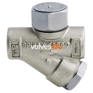
TLV HR80A alloy steel thermodynamic disc trap with thermostatic air venting. Features an air jacket, inline replaceable module, and handles up to 80 barg and 475 °C.
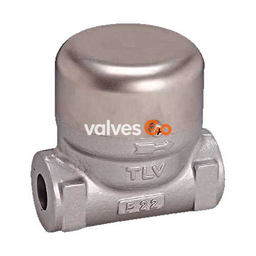
TLV HR80A is an alloy steel thermodynamic disc trap with thermostatic air venting, designed for the drainage of high-pressure and high-temperature steam mains and turbines. It features an air-jacketed design that reduces radiant heat loss, minimizing no-load cycling and extending the service life of the trap. The HR80A operates within a pressure range of 0.8 to 80 barg (0.08 to 8.0 MPaG) and can handle maximum operating temperatures up to 475 °C.
The trap incorporates an inline replaceable valve module for ease of maintenance and lower repair costs. A bimetal ring provides quick thermostatic air venting for fast start-up and the elimination of air binding.
Related Models
The TLV HR-A series also includes the HR150A (up to 150 barg) and HR260A (up to 260 barg, suitable for supercritical steam). This page focuses on the HR80A specifications.
| Connection | Socket Welded | Butt Welded | Flanged |
|---|---|---|---|
| Size | DN 15, 20, 25 | DN 15, 25 | DN 15, 20, 25 |
| Maximum Operating Pressure (PMO) | 80 barg | 80 barg | 80 barg |
| Minimum Operating Pressure | 8 barg | 8 barg | 8 barg |
| Maximum Operating Temperature (TMO) | 475 °C | 475 °C | 475 °C |
| Maximum Allowable Pressure (PMA) | 102 barg @ 40 °C | 102 barg @ 40 °C | 102 barg @ 40 °C |
| Maximum Allowable Temperature (TMA) | 550 °C @ 31 barg | 550 °C @ 31 barg | 550 °C @ 31 barg |
| Maximum Back Pressure | 50% of Inlet Pressure | 50% of Inlet Pressure | 50% of Inlet Pressure |
WARNING
Maximum allowable pressure (PMA) and maximum allowable temperature (TMA) are PRESSURE SHELL DESIGN CONDITIONS, NOT OPERATING CONDITIONS. To avoid abnormal operation, accidents, or serious injury, DO NOT use this product outside of the specification range.

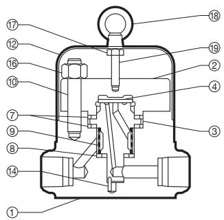
| No. | Description | Material | DIN | ASTM/AISI |
|---|---|---|---|---|
| 1 | Body | Alloy Steel A182 F22 Cl.3 | 1.7380 | A182 F22 Cl.3 |
| 2 | Cover | Stainless Steel SUS403 | 1.4000 | AISI403 |
| 3 | Module Valve Seat | Stainless Steel SUS440C | 1.4125 | AISI440C |
| 4 | Disc | Stainless Steel SUS440C | 1.4125 | AISI440C |
| 5 | Air Vent Ring | Bimetal | - | - |
| 6 | Disc Holder Ring | Stainless Steel SUS630 | 1.4542 | AISI630 |
| 7 | Module Gasket (large) | Graphite/Stainless Steel | -/1.4833 | -/AISI309S+Cb |
| 8 | Module Gasket (small) | Graphite/Stainless Steel | -/1.4833 | -/AISI309S+Cb |
| 9 | Screen inside/outside | Stainless Steel SUS430/304 | 1.4016/1.4301 | AISI430/304 |
| 10 | Cover Bolt | Alloy Steel SNB16 | 1.7711 | A193 Gr.B16 |
| 11 | Nameplate | Stainless Steel SUS304 | 1.4301 | AISI304 |
| 12 | Cap | Stainless Steel SUS304 | 1.4301 | AISI304 |
| 13 | Set Screw | Stainless Steel SUS304 | 1.4301 | AISI304 |
| 14 | Guide Pin | Stainless Steel SUS304 | 1.4301 | AISI304 |
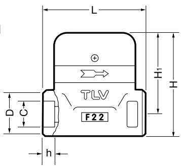
| DN | L (mm) | H (mm) | H1 (mm) | φD (mm) | φC (mm) | h (mm) | Weight (kg) |
|---|---|---|---|---|---|---|---|
| 15 | 110 | 115 | 90 | 48 | 21.8 | 14 | 3.9 |
| 20 | 110 | 115 | 90 | 48 | 27.2 | 14 | 3.8 |
| 25 | 110 | 115 | 90 | 48 | 33.9 | 14 | 3.7 |
| (ASME B16.11-2005, other standards available) |
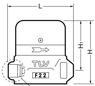
| DN | L (mm) | H (mm) | H1 (mm) | φD (mm) | φd (mm) | h (mm) | Weight (kg) |
|---|---|---|---|---|---|---|---|
| 15 | 110 | 115 | 90 | 22 | 17 | 20 | 3.8 |
| 25 | 110 | 115 | 90 | 34 | 28 | 20 | 3.8 |
| (DIN 3239 Form C (PN 100), other standards available) |
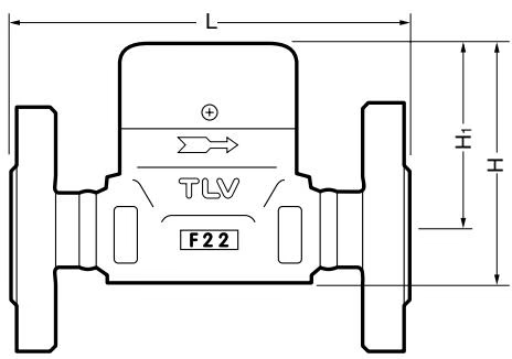
| DN | L (150RF) | L (300RF) | L (600RF) | L (900RF) | H (mm) | H1 (mm) | Weight* (kg) |
|---|---|---|---|---|---|---|---|
| 15 | 180 | 180 | 180 | 210 | 150 | 90 | 9.6 |
| 20 | 190 | 190 | 190 | 220 | 150 | 90 | 11 |
| 25 | 220 | 220 | 220 | 230 | 150 | 90 | 14 |
| Weight is for Class 900RF. |
Start-up Procedure
To ensure proper operation, slowly open the inlet valve slightly. Initially OPEN THE VALVE ONLY 1/32 TURN in order to supply steam to the trap very slowly, then WAIT FOR AT LEAST 30 SECONDS for air to vent before fully opening the inlet valve.
Operational inspections should be performed at least twice per year, or as called for by trap operating conditions.
| Part | Inspection Procedure |
|---|---|
| Sealing surfaces | Check for damage or dirt on the sealing surfaces |
| Screen | Check for clogging or corrosion damage |
| Bimetal ring | Check for rust, scale, oil film, warping or damage |
| Disc holder | Check for rust, scale, oil film, warping or damage |
| Disc | Check for wear and damage, scratches, on the surface where it contacts the valve seat, and dirt or oil film |
| Module valve seat | Check discharge channel and grooves for rust and scale inside |
| Body, Cover | Check inside for erosion, dirt, grease, rust or scale |
| Problem | Cause | Remedy |
|---|---|---|
| No condensate is discharged (blocked) or discharge is poor | Screen is clogged with rust or scale | Clean |
| Air vent ring (bimetal) is broken or worn, causing air-binding | Replace air vent ring | |
| Disc holder ring is broken or worn, causing air-binding | Replace disc holder ring | |
| Disc is sticking to valve seat (due to oil, etc.) | Clean | |
| Steam-locking has occurred | Perform a bypass blow-down, or close the trap inlet valve and allow the trap to cool. Piping correction may also be required. | |
| Trap capacity is insufficient | Change to trap of suitable capacity | |
| Differential pressure is low | Study inlet/outlet pressure, including rise in outlet pipe | |
| Steam leakage or blowing (from valve seat) | Valve closure is obstructed by scale, etc. | Clean or replace screen |
| Disc or valve seat is worn | Replace worn parts | |
| Air vent ring (bimetal) or disc holder ring is broken, obstructing valve closure | Replace air vent ring or disc holder ring | |
| Back pressure exceeds allowable value | Use within pressure range | |
| Trap is being used below minimum operating pressure | Use within pressure range | |
| Disc is sticking to top of cover (due to oil, etc.) | Clean | |
| Valve chattering (Leakage) | Foreign matter or oil film on disc or valve seat | Clean |
| Scratches on disc or valve seat | Replace disc or module valve seat | |
| Disc or valve seat is worn | Replace disc or module valve seat | |
| Leakage from a location other than valve seat | Bypass valve is damaged or open | Replace or close bypass valve |
| Cover is loose or module gaskets are damaged | Tighten cover or replace module gaskets |
Explore similar products in our catalog