ENP Nickel Plating

The Armstrong CD-4080 is a durable, high-pressure disc steam trap featuring a 360° universal connector block, replaceable seat, and 1245 psig max operating pressure.
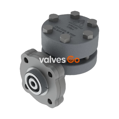
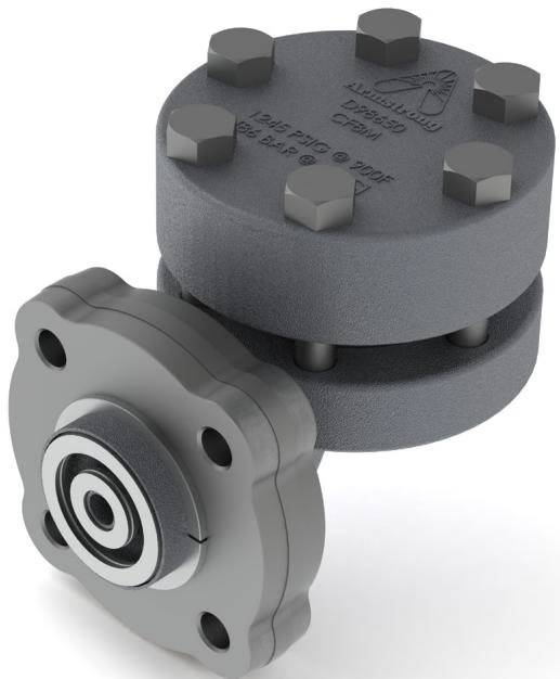
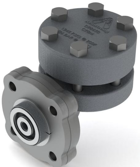
The Armstrong CD-4080 is a durable disc-style steam trap designed for high-pressure use. Engineered to meet the demanding conditions found in power plant, refinery, and chemical plant applications, the CD-4080 is piped in-line by a 360° four-bolt connector block (such as the Armstrong model IS-4). This allows the trap to be installed in virtually any piping configuration with the added flexibility of easier field replacement. For best performance, the CD-4080 should be mounted horizontally.
The CD-4080 disc steam trap combines savings in three important areas: energy, installation, and replacement. It features a compact design, exceptional corrosion resistance, freeze resistance, and a replaceable seat and disc. Mounting the CD-4080 on an IS-4 4-bolt connector provides quick and easy in-line replacement.
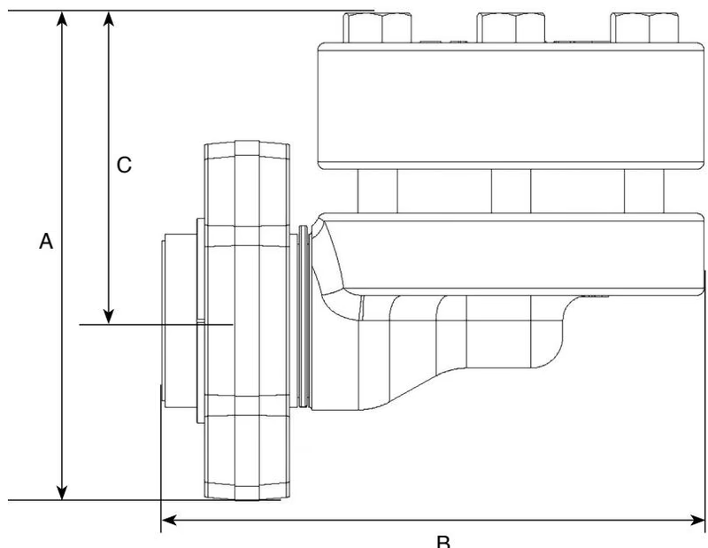
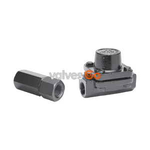
The trap utilizes a 360° universal connector block with the following options:
| Model No. | CD4080 (in) | CD4080 (mm) |
|---|---|---|
| Pipe Connections | 3/4, 1 | 20, 25 |
| “A” (Height) | 3.86 | 98.00 |
| “B” (Length) | 4.30 | 109.10 |
| “C” (Flange to Top) | 2.43 | 61.80 |
| Trap Only Weight lb (kg) | 5.2 | (2.3) |
WARNING
When working with high pressure/temperature steam, please review General Safety Guidelines. Before installation, verify that the maximum allowable pressure/temperature and maximum operating pressure of the trap are sufficient to handle the system design pressure and temperature.
BURN HAZARD
Due to the high temperatures of steam, the trap surface will be hot. For personnel safety, ensure proper precaution is taken while working near the steam trap. Contact with steam, hot water, or hot metal surfaces can cause severe skin burns.
Note: Drip leg pipe size (D) is the same as the header diameter up to 4" NPS. Above 4’’, use 1/2 the header size, but never less than 4’’.
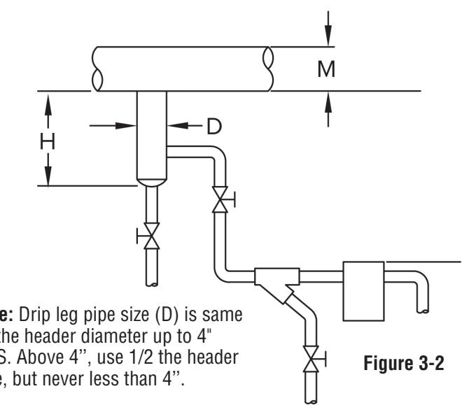
| Steam Main Size (in) NPS | Drip Leg Diameter (in) NPS | Supervised Warm-Up Min Length (in) | Automatic Warm-Up Min Length (in) |
|---|---|---|---|
| 1/2 | 1/2 | 10 | 28 |
| 3/4 | 3/4 | 10 | 28 |
| 1 | 1 | 10 | 28 |
| 2 | 2 | 10 | 28 |
| 3 | 3 | 10 | 28 |
| 4 | 4 | 10 | 28 |
| 6 | 4 | 10 | 28 |
| 8 | 4 | 12 | 28 |
| 10 | 6 | 15 | 28 |
| 12 | 6 | 18 | 28 |
| 14 | 8 | 21 | 28 |
| 16 | 8 | 24 | 28 |
| 18 | 10 | 27 | 28 |
| 20 | 10 | 30 | 30 |
| 24 | 12 | 36 | 36 |
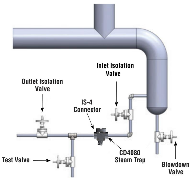
The IS-4 connector block should be installed in piping with the flow direction stamp pointing in the direction of steam flow as indicated on the connector block. The trap will then be bolted to the connector block after the connector block has been installed.
When installing the trap to the connector block, apply 35-50 lbf-ft (47 to 68 N-m) of torque to the bolts using a 3/8” wrench. Allow 3” (80 mm) clearance for bolt installation and removal.
In order to ensure continuous optimum performance from any steam trap, it should be inspected according to the following schedule:
| Operating Pressure (psig) | Drip | Tracer | Coil | Process | Critical Drip, Tracer, Coil or Process |
|---|---|---|---|---|---|
| 0-100 | 1 | 1 | 2 | 3 | 4 or Continuous Real Time Monitoring |
| 101-250 | 2 | 3 | 2 | 3 | 4 or Continuous Real Time Monitoring |
| 251-450 | 2 | 3 | 3 | 4 | 4 or Continuous Real Time Monitoring |
| 451 and above | 3 | 4 | 4 | 4 | 4 or Continuous Real Time Monitoring |
Note: Wear progresses simultaneously on both the disc and the seating surfaces. Simply replacing the disc is not sufficient to repair a disc trap. Replace the disc, seat and gaskets with a CD-4080 Series Repair Kit if the disc/seat are not sealing due to wear.
NOTE
It is not necessary to remove the connector block from the piping to install the replacement trap.
Explore similar products in our catalog