ENP Nickel Plating

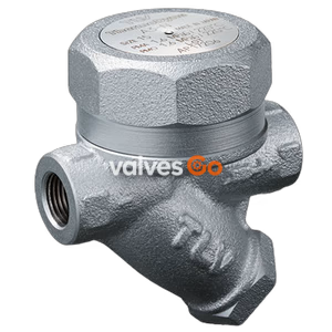
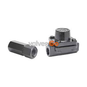
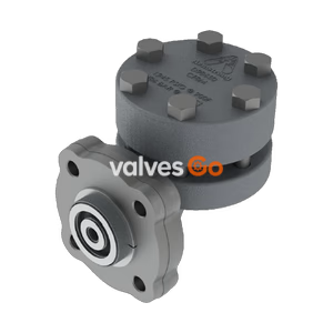
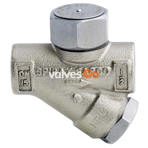
TLV P46SRM inline repairable thermodynamic disc trap with thermostatic air venting. Features carbon or stainless steel construction, max operating pressure of 46 barg, and max temperature of 425°C.
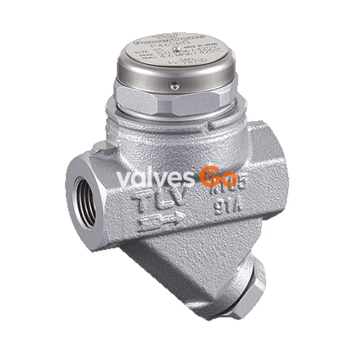
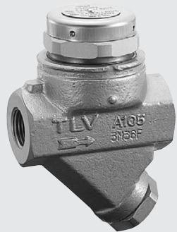
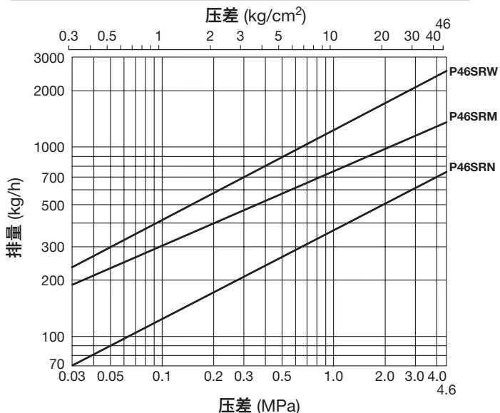
The TLV P46SRM is an inline repairable thermodynamic disc steam trap with thermostatic air venting. It is designed for medium capacity applications between 0.03 and 46 barg, such as steam mains, tracers, and coils. The trap discharges condensate at a temperature slightly lower than the saturation temperature and features a bimetal ring that provides quick thermostatic air venting to reduce start-up times.
Safety Considerations
Install properly and DO NOT use this product outside the recommended operating pressure, temperature and other specification ranges. Improper use may result in hazards such as damage to the product or malfunctions. When disassembling or removing the product, wait until the internal pressure equals atmospheric pressure and the surface of the product has cooled to room temperature to prevent burns from fluid discharge.
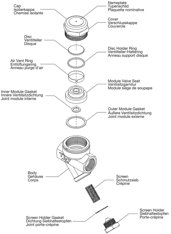
| No. | Description | No. | Description |
|---|---|---|---|
| 1 | Body | 8 | Nameplate |
| 2 | Module Valve Seat | 9 | Inner Module Gasket |
| 3 | Cover | 10 | Screen |
| 4 | Disc | 11 | Screen Holder Gasket |
| 5 | Disc Holder Ring | 12 | Screen Holder |
| 6 | Air Vent Ring (Bimetal) | 13 | Cap |
| 7 | Outer Module Gasket | 14 | Flange (Not shown) |
Screwed Connection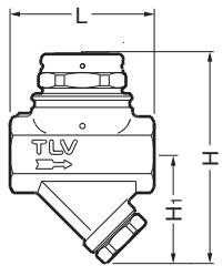
| Size | L (mm) | H (mm) | H1 (mm) | Weight (kg) |
|---|---|---|---|---|
| 1/2", 3/4" | 80 | 120 | 62 | 1.2 |
| 1" | 88 | 125 | 62 | 1.4 |
Socket Welded Connection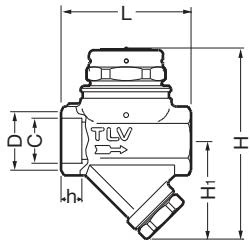
| DN | L (mm) | H (mm) | H1 (mm) | Weight (kg) |
|---|---|---|---|---|
| 15, 20 | 80 | 120 | 62 | 1.2 |
| 25 | 88 | 125 | 62 | 1.4 |
Flanged Connection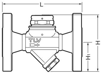
| DN | L (DIN 2501) | L (ASME 150RF) | L (ASME 300RF) | H (mm) | Weight (kg) |
|---|---|---|---|---|---|
| 15 | 150 | 140 | 140 | 120 | 2.7 - 3.3 |
| 20 | 150 | 165 | 165 | 120 | 3.7 - 4.7 |
| 25 | 160 | 210 | 210 | 120 | 5.0 - 6.1 |
Piping Arrangement Checks:
A visual inspection can be carried out to aid in determining the necessity for immediate maintenance or repair if the trap is open to atmosphere.
| Status | Description |
|---|---|
| Normal | Condensate is discharged in a short blast followed by a longer period of no drainage. Flash steam may be seen. |
| Blocked | No condensate is discharged. The trap is quiet and makes no noise. Surface temperature is low. |
| Blowing | Live steam continually flows from the outlet, and there is a continuous metallic sound. |
| Steam Leakage | Live steam is discharged through the trap outlet together with condensate, accompanied by a high-pitched sound. |
| Chattering | The trap does not close properly. Steam is discharged from the trap in short rapid bursts. |
Operational inspections should be performed at least twice per year. Before attempting to open the trap, close the inlet and outlet isolating valves and wait until the trap has cooled completely.
Disassembly / Reassembly:
| Problem | Cause | Remedy |
|---|---|---|
| No condensate is discharged (blocked) | Screen is clogged with rust or scale. | Clean. |
| Air vent ring or disc holder ring is broken, causing air-binding. | Replace ring. | |
| Steam-locking has occurred. | Perform a bypass blow-down, or close the trap inlet valve and allow the trap to cool. | |
| Steam leakage or blowing | Valve closure is obstructed by scale, etc. | Clean or replace screen. |
| Disc or valve seat is worn. | Replace worn parts. | |
| Back pressure exceeds allowable value. | Use within pressure range. | |
| Valve chattering | Foreign matter or oil film on disc or valve seat. | Clean. |
The BD2 Blowdown Valve, installed in place of the screen holder, uses internal pressure to blow out condensate/steam, dirt and scale to the atmosphere.

BD2 Operation
Always wear eye protection and heat-resistant gloves when operating the blowdown valve. Stand to the side well clear of the outlet to avoid contact with internal fluids that will be discharged. Do not excessively loosen the BD2 valve when opening.
To operate, firmly hold the BD2 Valve Seat (30 mm) in place while slowly opening the BD2 Valve (17 mm). Close the BD2 Valve and tighten to a torque of 30 N·m (22 lbf·ft).
Explore similar products in our catalog