ENP Nickel Plating

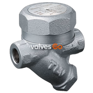
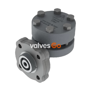
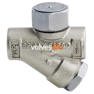
TLV FP46UC universal thermodynamic disc steam trap with thermostatic air venting. Features inline replaceable 2-bolt flange, high air venting, and stainless steel construction for steam mains and tracers.
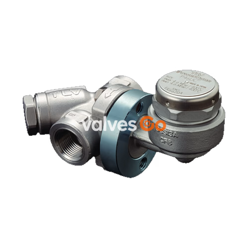
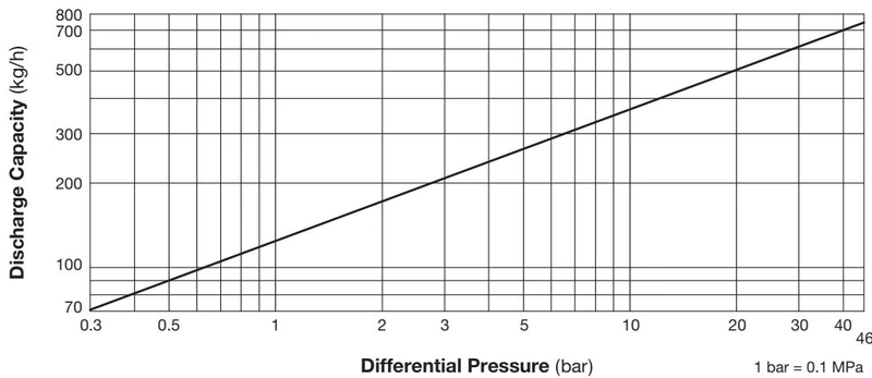
TLV FP46UC is a universal thermodynamic disc steam trap with thermostatic air venting. The FP46UC steam trap (connector body unit F46 or former connector body unit F32 and steam trap unit P46UC) can be used without adjustment for medium capacity applications between 0.03 and 4.6 MPaG (5 and 650 psig), such as steam mains, tracers, and coils. The trap discharges condensate at a temperature slightly lower than saturation temperature.
| Connection | Screwed | Socket Welded | Flanged |
|---|---|---|---|
| Size | 1/2", 3/4", 1" | DN 15, 20, 25 | DN 15, 20, 25 |
| Maximum Operating Pressure (PMO) | 4.6 MPaG | 4.6 MPaG | 4.6 MPaG |
| Minimum Operating Pressure | 0.03 MPaG | 0.03 MPaG | 0.03 MPaG |
| Maximum Operating Temperature (TMO) | 400 °C / 425 °C | 400 °C / 425 °C | 400 °C / 425 °C |
| Maximum Allowable Pressure (PMA) | 6.6 MPaG @ 40 °C | 6.6 MPaG @ 40 °C | 6.6 MPaG @ 40 °C |
| Maximum Allowable Temperature (TMA) | 400 °C / 425 °C @ 5.0 MPaG | 400 °C / 425 °C @ 5.0 MPaG | 400 °C / 425 °C @ 5.0 MPaG |
| Maximum Back Pressure | 80% of Inlet Pressure | 80% of Inlet Pressure | 80% of Inlet Pressure |
| Connector Unit | F46 | F46 | F46 |
| Trap Unit | P46UC | P46UC | P46UC |
INFO
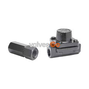
Designed for use with F46, F32 Connector Units and V1/V2 Trap Stations. Trap and Connector Units sent as separate units for flexible installation.
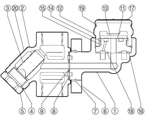
| No. | Description | Material | DIN | ASTM/AISI |
|---|---|---|---|---|
| 1 | Trap Body | Cast Stainless Steel A351 Gr.CF8 | 1.4312 | - |
| 2 | Connector Body | Cast Stainless Steel A351 Gr.CF8 | 1.4312 | - |
| 3 | Screen inside/outside | Stainless Steel SUS304/430 | 1.4301/1.4016 | AISI304/430 |
| 4 | Screen Holder Gasket | Stainless Steel SUS316L | 1.4404 | AISI316L |
| 5 | Screen Holder | Cast Stainless Steel A351 Gr.CF8 | 1.4312 | - |
| 6 | Connector Flange | Carbon Steel A105 | 1.0460 | - |
| 7 | Snap Ring | Carbon Steel SWRH57 | 1.0535 | AISI1055 |
| 8 | Outer Connector Gasket | Graphite/Stainless Steel SUS304 | - /1.4301 | -/AISI304 |
| 9 | Inner Connector Gasket | Graphite/Stainless Steel SUS304 | - /1.4301 | -/AISI304 |
| 10 | Connector Bolt | Carbon Steel SNB7 | 1.7225 | A193 Gr.B7 |
| 11 | Module Valve Seat | Stainless Steel SUS420F | 1.4028 | AISI420F |
| 12 | Cover | Stainless Steel A182 F304 | 1.4301 | - |
| 13 | Disc | Stainless Steel SUS420J2 | 1.4031 | AISI420 |
| 14 | Disc Holder Ring | Stainless Steel SUS420J2 | 1.4031 | AISI420 |
| 15 | Air Vent Ring | Bimetal | - | - |
| 16 | Outer Module Gasket | Graphite/Stainless Steel SUS316L | - /1.4404 | -/AISI316L |
| 17 | Nameplate | Stainless Steel SUS304 | 1.4301 | AISI304 |
| 18 | Inner Module Gasket | Graphite/Stainless Steel SUS316L | - /1.4404 | -/AISI316L |
| 19 | Cap | Stainless Steel SUS304 | 1.4301 | AISI304 |
| 20 | Connector Nameplate | Stainless Steel SUS304 | 1.4301 | AISI304 |
| 21 | Flange | Cast Stainless Steel A351 Gr.CF8/Stainless Steel SUS304 | 1.4312/1.4301 | -/AISI304 |
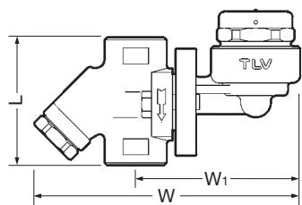
| Size | L (mm) | W (mm) | W1 (mm) | Weight (kg) |
|---|---|---|---|---|
| 1/2" | 80 | 168 | 104 | 1.7 |
| 3/4" | 80 | 168 | 104 | 1.7 |
| 1" | 96 | 172 | 110 | 2.0 |
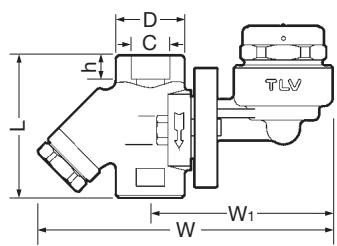
| DN | L (mm) | W (mm) | W1 (mm) | φD (mm) | φC (mm) | h (mm) | Weight (kg) |
|---|---|---|---|---|---|---|---|
| 15 | 80 | 168 | 104 | 36 | 21.8 | 12 | 1.7 |
| 20 | 80 | 168 | 104 | 36 | 27.2 | 14 | 1.7 |
| 25 | 96 | 172 | 110 | 44 | 33.9 | 14 | 2.0 |
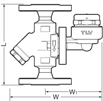
| DN | L (DIN 2501 PN25/40) | L (ASME 150RF) | L (ASME 300RF) | L (ASME 600RF) | W (mm) | W1 (mm) | Weight (kg) |
|---|---|---|---|---|---|---|---|
| 15 | 150 | 150 | 150 | 180 | 170 | 105 | 3.4 |
| 20 | 150 | 150 | 150 | 180 | 170 | 105 | 4.2 |
| 25 | 160 | 160 | 160 | 190 | 170 | 105 | 4.7 |
WARNING
Install properly and DO NOT use this product outside the recommended operating pressure, temperature and other specification ranges. Improper use may result in such hazards as damage to the product or malfunctions, which may lead to serious accidents.
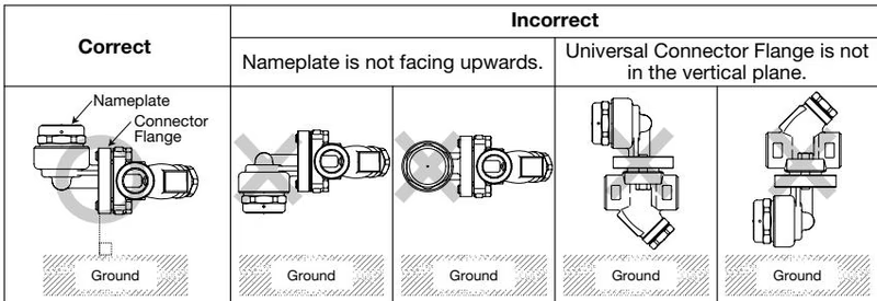
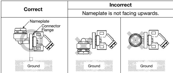
| Problem | Cause | Remedy |
|---|---|---|
| No condensate is discharged (blocked, or discharge is poor) | Screen is clogged with rust or scale | Clean |
| Air vent ring (bimetal) is broken or worn, causing air-binding | Replace air vent ring | |
| Disc holder ring is broken or worn, causing air-binding | Replace disc holder ring | |
| Disc is sticking to valve seat (due to oil, etc.) | Clean | |
| Steam-locking has occurred | Perform a bypass blowdown, or close the trap inlet valve and allow the trap to cool. Piping correction may also be required. | |
| Trap capacity is insufficient | Change to trap of suitable capacity | |
| Differential pressure is low | Study inlet/outlet pressure, including rise in outlet pipe | |
| Steam leakage or blowing (from valve seat) | Valve closure is obstructed by scale, etc. | Clean or replace screen |
| Disc or valve seat is worn | Replace worn parts | |
| Air vent ring (bimetal) or disc holder ring is broken, obstructing valve closure | Replace air vent ring or disc holder ring | |
| Back pressure exceeds allowable value | Use within pressure range | |
| Trap is being used below minimum operating pressure | Use within pressure range | |
| Disc is sticking to top of cover (due to oil, etc.) | Clean | |
| Valve chattering (Leakage) | Foreign matter or oil film on disc or valve seat | Clean |
| Scratches on disc or valve seat | Replace disc, valve seat, or trap unit | |
| Disc or valve seat is worn | Replace disc, valve seat, or trap unit | |
| Leakage from a location other than valve seat | Bypass valve is damaged or open | Replace or close bypass valve |
| Cover is loose or module gaskets are damaged | Tighten cover or replace module gaskets | |
| Cover is loose or sealing surface between cover and valve seat is damaged | Tighten or replace cover, or replace valve seat | |
| Connector bolts are loose or connector gaskets are damaged | Tighten connector bolts or replace connector gaskets | |
| Inlet and discharge channels may be connected, due to erosion | Replace trap (study trap capacity) | |
| Screen holder is loose or screen holder gasket is damaged | Tighten screen holder or replace screen holder gasket |
Explore similar products in our catalog