Cast Iron

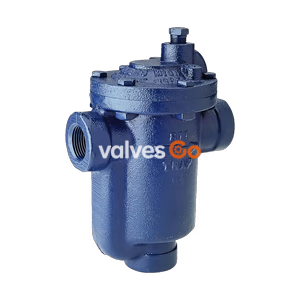
Armstrong 200 Series cast iron inverted bucket steam traps (Models 211-216) provide efficient condensate drainage with a free-floating stainless steel mechanism, handling up to 17 bar (250 psig).
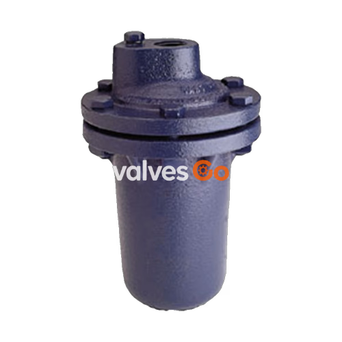
Armstrong 200 Series (Models 211-216) cast iron inverted bucket steam traps provide efficient condensate drainage for virtually all types of steam-using equipment. The inverted bucket is known as the most reliable steam trap operating principle, and putting it to work in a tough cast iron package offers solid energy savings and lower replacement/labor costs due to long, efficient operating periods.
A unique leverage system multiplies the force provided by the bucket to open the valve against system pressure. The mechanism is free-floating and has no fixed pivots to create wear or friction. Because the mechanism is located at the top of the trap, no dirt can collect on the orifice. Small particles of dirt are held in suspension until discharged by the full differential purging action when the bucket sinks, pulling the valve off the seat.
The discharge orifice is surrounded by a water seal, preventing live steam loss. Automatic air venting is provided by a small vent hole in the bucket, which provides continuous automatic air and CO₂ venting at steam temperature. Inverted bucket traps drain continuously, although discharging intermittently, allowing no condensate backup. They are also highly resistant to water hammer.
Table: 200 Series, Bottom Inlet, Top Outlet Trap (dimensions in mm)
| Model No. | 211 | 212 | 213 | 214 | 215 | 216 |
|---|---|---|---|---|---|---|
| Pipe Connections | 15 | 15 – 20 | 15 – 20 – 25 | 25 – 32 | 25 – 32 – 40 | 40 – 50 |
| Test plug | 1/8" | 3/8" | 1/2" | 1/2" | 3/4" | 1" |
| "A" Flange Diameter | 108 | 133 | 162 | 190 | 216 | 259 |
| "B" Face-to-Face (screwed) | 164 | 218 | 292 | 315 | 361 | 455 |
| Weight in kg (screwed) | 2.7 | 5.2 | 9.2 | 15.0 | 20.3 | 35.2 |
Note
Add suffix "CV" to model number for internal check valve, "T" for thermic vent bucket; "LV" for the large vent. All dimensions and weights are approximate.
Before installing the trap, clean the line by blowing down with steam or compressed air. The trap should be easily accessible for inspection and repair, installed below the drip point whenever possible, and close to the drip point.
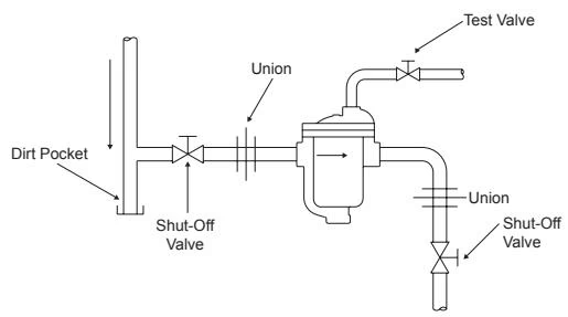
Standard Hookup: Shutoff valves ahead of traps are needed when the system cannot be shut down for trap maintenance. A shutoff valve in the trap discharge line is needed when the trap has a bypass or when there is high pressure in the discharge header. Unions should be at right angles – not inline – to facilitate trap removal.
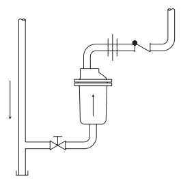
Anti-Freeze Precautions
Do not oversize the trap. Keep the discharge line very short and pitch it down for fast gravity drainage. Insulate trap discharge lines and condensate return lines. A long horizontal discharge line invites trouble as ice can form at the far end, eventually sealing off the pipe.
All repairable traps should be opened at least once a year to check the operating mechanism.
Internals Maintenance:

Valve Seat Installation
When installing valve seats, do NOT use any pipe dope or lubricant of any kind on the seat threads. The joint is made by the contact between the ground end of the valve seat and the beveled seating area at the bottom of the tapped hole. Make sure this seating area is perfectly clean.
The Test Valve Method is the best way to check trap operation. With a test valve in the return line downstream of the trap, look for intermittent condensate discharge. Do not mistake flash steam (which floats out intermittently in a whitish cloud) for a continuous live steam leak (which blows out continuously in a blue stream).
Explore similar products in our catalog