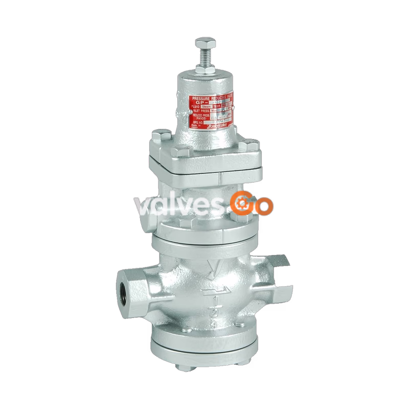
Yoshitake GP-1010 pressure reducing valves for steam are pilot-operated valves which can be used with confidence for small to large flow rates, in a host of applications ranging from building utilities systems, air-conditioning systems, and factory systems.
Features
- Significantly improved workability and durability compared with conventional pressure reducing valves.
- Spherical main valve offers great sealability and great reduction of valve seat leakage (compliant with ANSI Class IV).
- Compliant with SHASE-S106 Pressure Reducing Valves (by the Society of Heating, Air-Conditioning and Sanitary Engineers of Japan).
- Simple and robust internal structure.
Specifications
| Item | Specification |
|---|
| Application | Steam |
| Inlet pressure | 0.1 - 1.0 MPa |
| Reduced pressure | 0.05 - 0.9 MPa (90% or less of inlet pressure) |
| Minimum differential pressure | 0.05 MPa |
| Maximum pressure reduction ratio | 20:1 |
| Maximum temperature | 220°C |
| Valve seat leakage | 0.01% or less of rated flow |
| Connection | JIS Rc Screw |
Materials
| Part | Material |
|---|
| Body | Ductile cast iron |
| Valve, Valve seat | Stainless steel |
| Piston, Cylinder | Brass or Bronze |
| Gasket | Non asbestos |
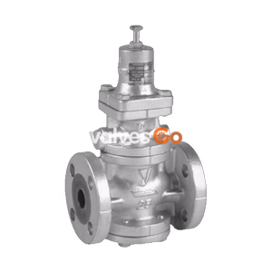
Note: The GP-1000 series is available in flanged connections. All-stainless steel (GP-1000AS) or stainless steel wetted parts (GP-1000SS) are also available. For GP-1010, adjusting handle types are available as GP-1011.
Dimensions and Weights
| Nominal size | d | L (mm) | H1 (mm) | H (mm) | Weight (kg) |
|---|
| 15A | Rc 1/2 | 150 | 64 | 285 | 7.0 |
| 20A | Rc 3/4 | 155 | 64 | 285 | 7.0 |
| 25A | Rc 1 | 160 | 67 | 300 | 8.5 |
| 32A | Rc 1-1/4 | 190 | 82 | 323 | 12.0 |
| 40A | Rc 1-1/2 | 190 | 82 | 323 | 12.5 |
| 50A | Rc 2 | 220 | 93 | 347 | 18.0 |
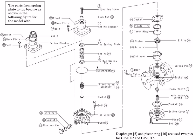
Operation
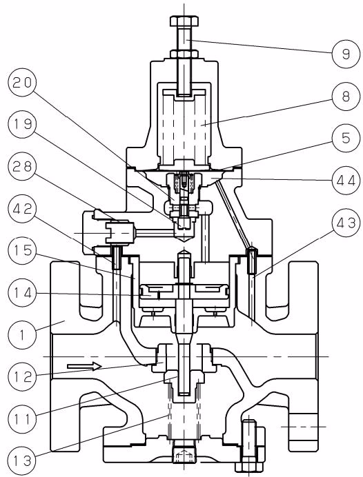
| No. | Parts name | No. | Parts name |
|---|
| 1 | Body | 15 | Cylinder |
| 5 | Diaphragm | 19 | Pilot valve |
| 8 | Adjusting spring | 20 | Pilot valve seat |
| 9 | Adjusting screw | 28 | Strainer |
| 11 | Main valve | 42 | Inlet press. passage |
| 12 | Main valve seat | 43 | Reduced press. sensing port |
| 13 | Main valve spring | 44 | Diaphragm chamber |
| 14 | Piston | | |
The pressure-reducing valve reduces pressure by throttling the valve. The valve is composed of the main valve and main valve seat for throttling, and an adjusting spring, diaphragm, pilot valve, and piston for pressure sensing and activation.
- When the pressure-reducing valve is mounted correctly, releasing the compression of the adjusting spring allows the spring to close the main valve and pilot valve. Slowly open the gate valve and allow the high-pressure fluid to flow in. Inlet pressure is applied to the downside of the main valve. High-pressure fluid passes through the strainer via the inlet pressure passage to also apply inlet pressure to the downside of the pilot valve.
- Turning the adjusting screw clockwise compresses the spring, which flexes the diaphragm to open the pilot valve.
- Inlet pressure via the inlet pressure passage and pilot valve enters the upside of the piston. The pressure overrides the pressure on the downside of the main valve and the load of the main valve spring, to open the main valve. The fluid then begins to flow from the inlet side.
- Reduced pressure is led to the diaphragm chamber via the reduced pressure sensing port. The diaphragm receives the reduced pressure to be balanced with the adjusting spring load, and controls the pilot valve travel.
- The change of pilot valve travel changes the flow rate of fluid to the upside of the piston, and controls the main valve travel to obtain the appropriate reduced pressure.
Nominal Size Selection
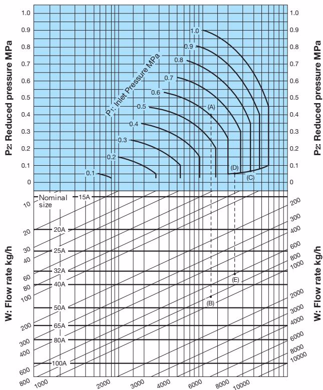
When selecting the nominal size of a pressure reducing valve whose inlet pressure (P1), reduced pressure (P2), and steam flow rate are 0.8 MPa, 0.05 MPa, and 600 kg/h, respectively:
- Find intersection point (C) of the inlet pressure of 0.8 MPa and the diagonal line.
- Trace down to the left from this intersection point to find intersection point (D) with the reduced pressure of 0.05 MPa.
- Trace down vertically from intersection point (D) to find intersection point (E) with the flow rate of 600 kg/h.
- Since intersection point (E) lies between nominal sizes 32A and 40A, select the larger one, 40A.
Safety Factor
Set the safety factor at 80 to 90%.
Installation
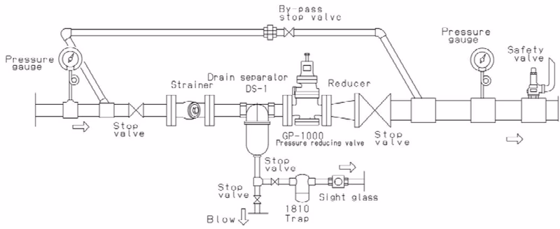
Precautions during installation
- Because of heavy weight, hold the valve with lifting equipment while piping.
- Install a strainer (Recommendation: 80-100mesh or equivalent) at the valve inlet side.
- Install a safety valve at the valve outlet sides as a safety device for equipment.
- Install a pressure gauge at both the inlet and outlet sides of the valve.
- Install a steam trap to the inlet sides of the valve to prevent drainage problems.
- When installing quick open and close valves, such as a solenoid valve, secure at least 3 m from the valve.
- When pressure reducing in two stages, secure at least 3 m between the valves.
- Provide a by-pass line.
- Provide space on the top and bottom of the valve so that the valve can be easily disassembled and inspected.
Maintenance
Consumable parts replacement periods:
- Diaphragm: 2 years
- Piston ring: 3 years
- Inner ring: 3 years
- Pilot valve assembly: 5 years
- Gaskets: 2 years
- Strainer: 5 years