
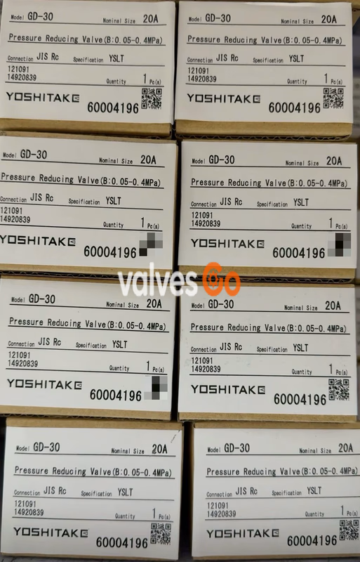


PN25

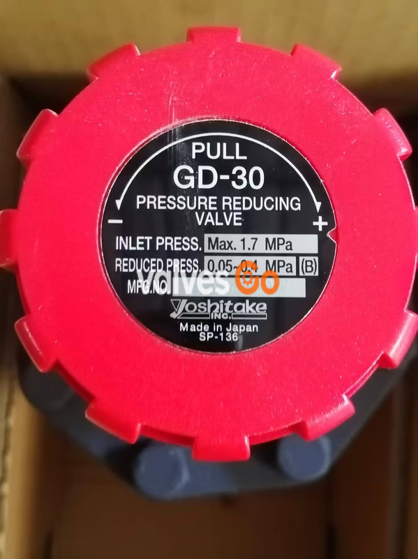
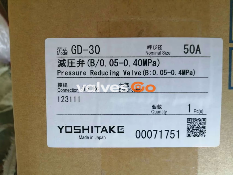
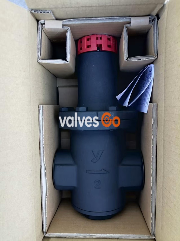
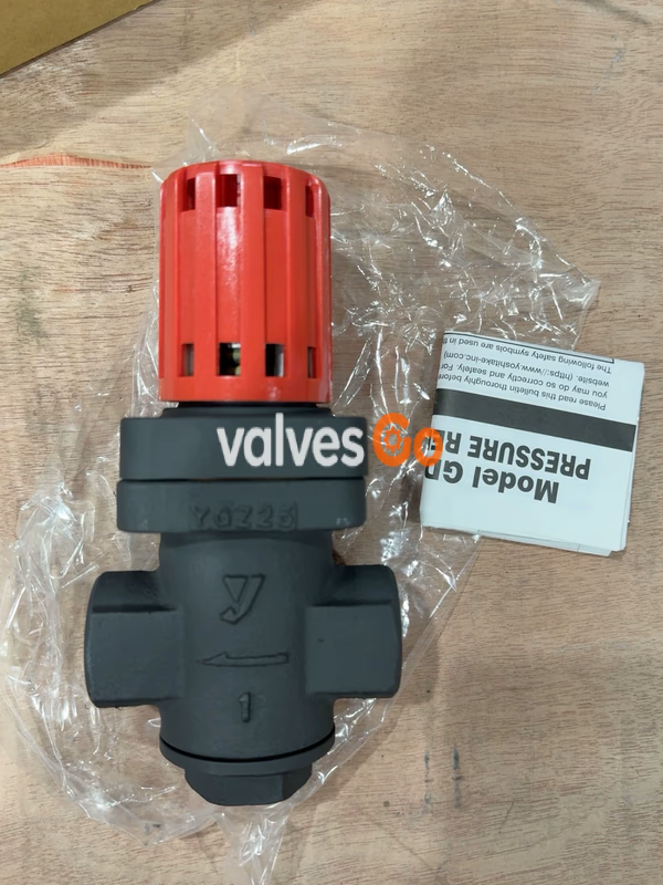
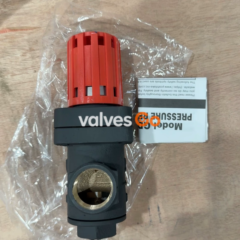
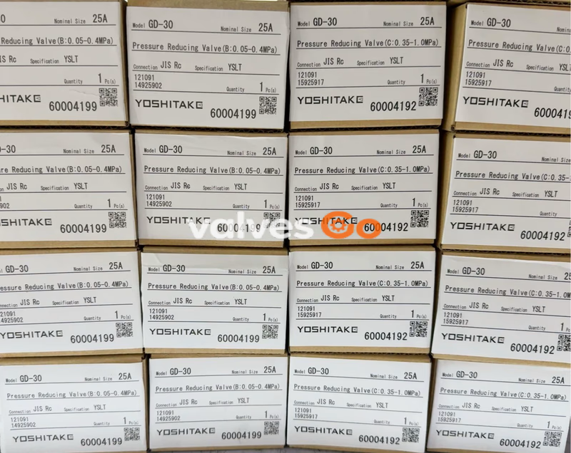
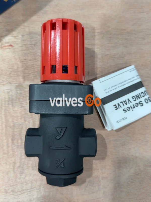
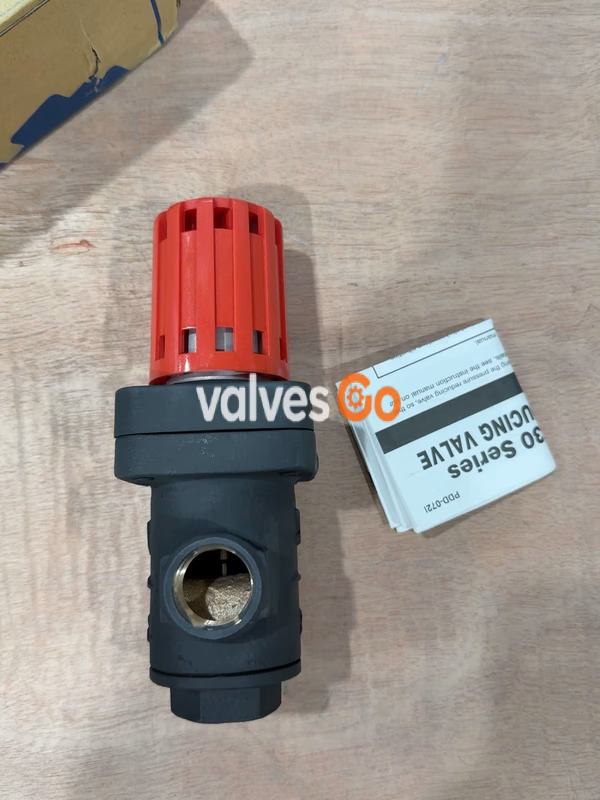
Yoshitake GD-30 direct-type, handle-operated pressure reducing valve for steam. Features a cast bronze body, external pressure bellows, and built-in strainer. Handles up to 1.7 MPa inlet pressure.
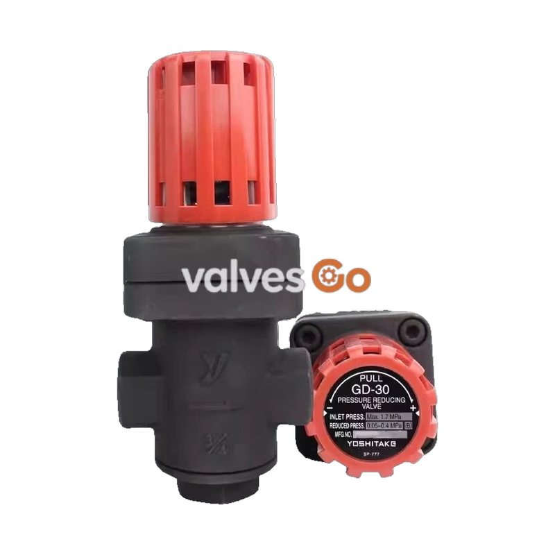
Yoshitake GD-30 is a direct-type pressure reducing valve designed specifically for steam applications. It utilizes an external pressure type bellows for internal sensing and is equipped with a built-in 60 mesh strainer to protect the stainless steel valve and valve seat from dirt. Pressure adjustment is easily handled without the need for tools, making it a highly reliable and maintenance-friendly choice for industrial steam control.
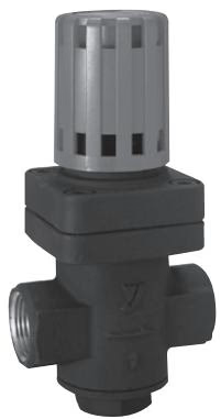
| Specification | GD-30 | GD-30S |
|---|---|---|
| Nominal Size | 15A-25A, 40A-50A | 15A-25A |
| Fluid | Steam | Steam |
| Inlet Pressure | 1.7 MPa or less | 2.0 MPa or less |
| Reduced Pressure | (A) 0.02-0.1 MPa (yellow spring) (B) 0.05-0.4 MPa (blue spring) (C) 0.35-1.0 MPa (yellow-green spring) | (A) 0.02-0.1 MPa (B) 0.05-0.4 MPa (C) 0.35-1.0 MPa |
| Min. Differential Pressure | 0.05 MPa | 0.05 MPa |
| Max. Pressure Reduction Ratio | 10:1 | 10:1 |
| Maximum Temperature | 210°C | 220°C |
| Valve Seat Leakage | 0.1% or less of rated flow rate | 0.1% or less of rated flow rate |
| Body Material | Cast bronze | Cast stainless steel (SCS14A) |
| Valve, Valve Seat | Stainless steel | Stainless steel |
| Bellows | Phosphor bronze | Stainless steel |
| Connection | JIS Rc screwed, NPT, BSPT | JIS Rc screwed |
| Nominal Size | d | L (mm) | H1 (mm) | H (mm) | Weight (kg) |
|---|---|---|---|---|---|
| 15A | Rc 1/2, NPT 1/2, BSPT 1/2 | 80 | 47 (50.5) | 191 (196) | 1.9 |
| 20A | Rc 3/4, NPT 3/4, BSPT 3/4 | 85 | 47 (50.5) | 191 (196) | 1.9 |
| 25A | Rc 1, NPT 1, BSPT 1 | 95 | 47 (50.5) | 191 (196) | 2.0 |
| 40A | Rc 1-1/2, NPT 1-1/2, BSPT 1-1/2 | 140 | 77 | 307 | 10.1 |
| 50A | Rc 2, NPT 2, BSPT 2 | 150 | 77 | 307 | 10.4 |
Note: The values in parentheses are the dimensions of the GD-30S.
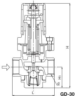
When the adjusting screw connected to the handle pushes the adjusting spring, the bellows are extended and the spindle opens the valve. When the valve opens, the steam flowing to the outlet side passes through the reduced pressure detection hole, and becomes an upwardly directed pressure under the bellows and balances the force of the adjusting spring. The degree of valve opening is adjusted by the balancing of inlet and reduced pressures, thereby stabilizing reduced pressure.
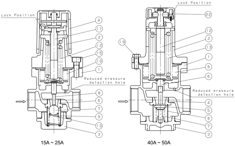
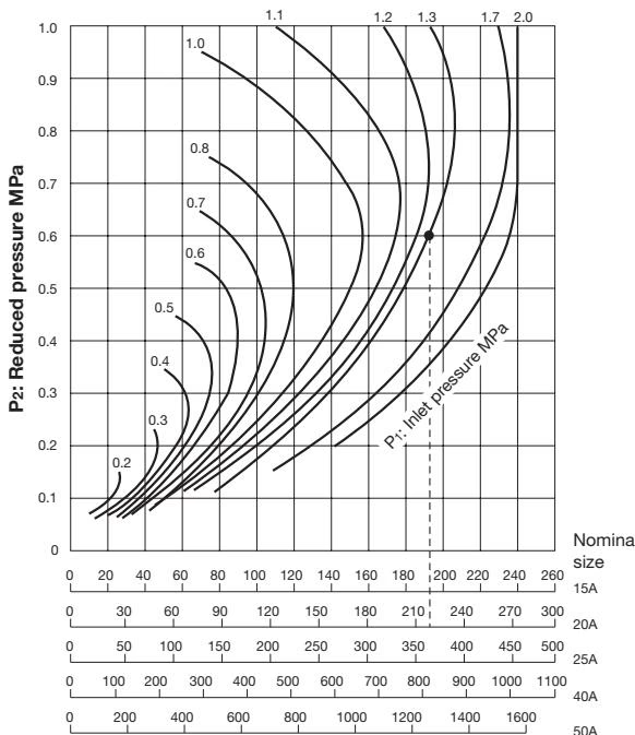
Note: 40A and 50A have a different structure and utilize the chart below:
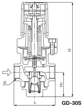
Selection Example
When selecting the nominal size of a pressure reducing valve whose inlet pressure (P1), reduced pressure (P2), and flow rate are 1.3 MPa, 0.6 MPa, and 200 kg/h, respectively, first find the intersection point of the inlet pressure of 1.3 MPa and the reduced pressure of 0.6 MPa. Trace down vertically from this intersection point to find the nominal size with a flow rate of 200 kg/h or over. In this case, the nominal size is 20A.
The nominal sizes selection chart is based on measured data. Set the safety factor at 80% to 90%.
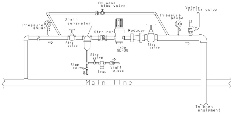
Safety Relief Valve Piping
In case installing a safety valve as a safety device at the outlet side, joint a relief pipe at the outlet of the safety valve and guide it to a safe place where steam can safely relief out. Failure to do so may result in burns.
Installation Guidelines
Burn Hazard
Do not touch the valve directly with bare hands. Doing so may result in burns. Before allowing steam in the pipeline, make sure steam can flow safely at the end of the pipeline and that the pipeline is connected tightly.
Pre-operation Steps
Close the stop valves before and after the reducing valve, and remove all foreign matter and scales via the bypass line before operation. Open each stop valve slowly to prevent hunting or water hammer.
Handle Adjustment Precaution
Excessive turning of the handle may damage the spring chamber. Be sure to turn the handle within the range where the spring plate and spring chamber do not come into contact with each other.
Note for 40A and 50A sizes: There is a possibility that the handle is stuck and cannot be removed. It is easier to turn the handle to obtain high reduced pressure if a screwdriver (axis diameter φ6) is inserted through the notches and turned left or right.
| Problem | Cause | Solution |
|---|---|---|
| Pressure does not rise to the desired level | Incorrect pressure is used. Nominal size is too small. Incorrect adjustment. Screen is clogged. Pressure gauge malfunction. | Correct the pressure. Replace with correct nominal size. Re-adjust. Disassemble and clean. Replace gauge. |
| Reduced pressure exceeds prescribed level | Foreign matter is embedded in valve/seat, or scratches exist. Sensing hole is clogged. By-pass valve is leaking. | Disassemble and clean. If scratches exist, polish them away. Disassemble and clean. Repair or replace the valve. |
| Abnormal noise is heard | Pressure reduction ratio is too large. Drainage problem. An abrupt open/close valve is located too close. | Use a two-stage reduction. Install a trap. Maximize distance between the valves. |
Residual Pressure Hazard
Completely discharge internal pressure from the valves, lines, and equipment, and cool the valve down to a level where you can touch it with bare hands before disassembly and inspection. Failure to do so may result in injury or burns due to residual pressure or steam spillage.
Disassembly Precautions
For 15A, 20A, 25A: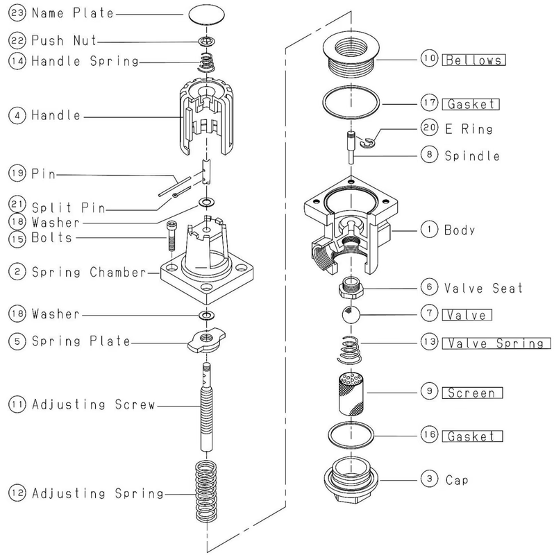
For 40A, 50A: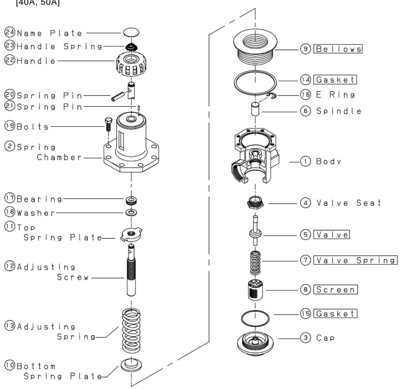
(Part names shown in boxes in the source drawings are consumable items)
Yoshitake Control Valves / Pressure Reducing Valves
GP, GD, and CP series for stable pressure reduction and control in steam, water, and air systems.
Explore similar products in our catalog



