PN25
Yoshitake GD-41N and GD-43N series direct type pressure reducing valves feature stainless steel wetted parts, PTFE diaphragms, and JWWA approval for cold and hot water.
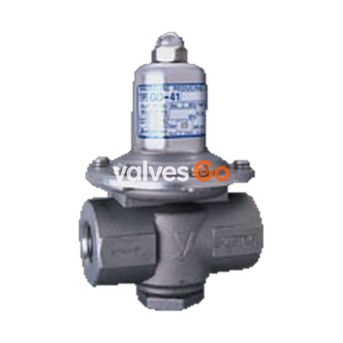
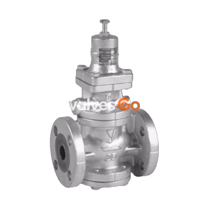
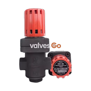
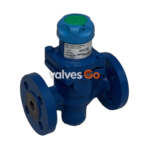
Yoshitake GD-41N series are direct type pressure reducing valves designed specifically for cold and hot water applications. The GD-41N (screwed connection) and its flanged counterpart, the GD-43N, conform to the Japanese Water Supply Act (JWWA) and feature wetted parts made of stainless steel (SCS14A and SUS316) for superior corrosion resistance. A pressure balance structure is incorporated to maintain a constant reduced pressure regardless of fluctuations in the inlet pressure, making them highly reliable in plumbing and water supply systems.
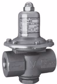 GD-41N
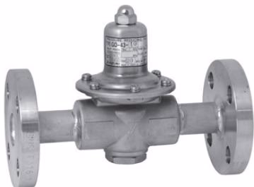 GD-43N
| Specification | GD-41N | GD-43N-10 | GD-43N-20 |
|---|---|---|---|
| Connection | JIS Rc screwed | JIS 10K FF Flanged | JIS 20K RF Flanged |
| Nominal Size | 15A, 20A, 25A | 15A, 20A, 25A | 15A, 20A, 25A |
| Application Fluid | Cold and hot water | Cold and hot water | Cold and hot water |
| Inlet Pressure | 0.07 - 2.0 MPa | 0.07 - 1.0 MPa | 0.07 - 2.0 MPa |
| Reduced Pressure | Spring A (yellow): 0.02-0.1 MPa Spring B (red): 0.1-0.25 MPa Spring C (black): 0.25-0.5 MPa | Spring A (yellow): 0.02-0.1 MPa Spring B (red): 0.1-0.25 MPa Spring C (black): 0.25-0.5 MPa | Spring A (yellow): 0.02-0.1 MPa Spring B (red): 0.1-0.25 MPa Spring C (black): 0.25-0.5 MPa |
| Min. Differential Pressure | 0.05 MPa | 0.05 MPa | 0.05 MPa |
| Max. Reduction Ratio | 10:1 | 10:1 | 10:1 |
| Operating Temperature | 5 - 90°C | 5 - 90°C | 5 - 90°C |
| Cv Value | 15A: 0.4, 20A: 0.6, 25A: 0.8 | 15A: 0.4, 20A: 0.6, 25A: 0.8 | 15A: 0.4, 20A: 0.6, 25A: 0.8 |
| Pressure Characteristic | Set pressure ±0.05 MPa | Set pressure ±0.05 MPa | Set pressure ±0.05 MPa |
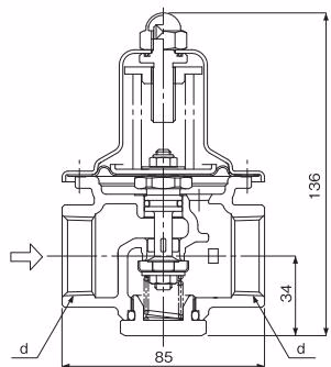
| Nominal Size | d | Weight (kg) |
|---|---|---|
| 15A | Rc 1/2 | 1.2 |
| 20A | Rc 3/4 | 1.1 |
| 25A | Rc 1 | 1.0 |
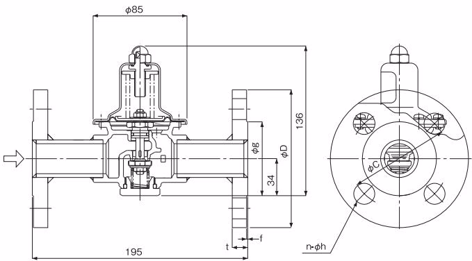
| Size | D | C | g | t | f | n-h | Weight (kg) |
|---|---|---|---|---|---|---|---|
| 15A | 95 | 70 | 51 | 14 (12) | 1 | 4-15 | 2.8 (2.6) |
| 20A | 100 | 75 | 56 | 16 (14) | 1 | 4-15 | 3.0 (2.9) |
| 25A | 125 | 90 | 67 | 16 (14) | 1 | 4-19 | 4.0 (3.7) |
(Note: Values in parentheses are the weights and dimensions for the GD-43N-10 10K version. All other dimensions represent JIS 20K RF flange).
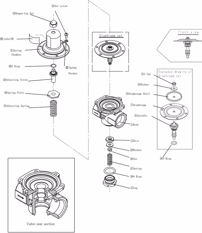
| Component | Material |
|---|---|
| Body / Cap | Cast Stainless Steel (SCS14A) |
| Spring Chamber | Stainless Steel (SUS316) |
| Disc (Valving Element) | Special Synthetic Rubber (FKM) & Stainless Steel (SUS304) |
| Spindle | Cast Stainless Steel (SCS14A) |
| Diaphragm | Heat-resistant Synthetic Rubber (FKM) and PTFE |
| Diaphragm Shell | Stainless Steel (SUS316) |
| Adjusting Spring | Alloy Steel (SWOSC-V) |
| Adjusting Screw | Brass (C3604) |
| O-Rings | FKM |
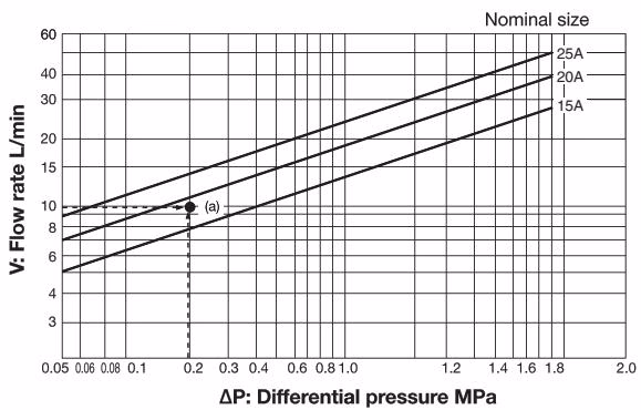
Selection Example: To determine the nominal diameter for a pressure reducing valve with a primary pressure of 0.5 MPa, a secondary pressure of 0.3 MPa, and a flow rate of 40 m³/h (standard condition):
Performance Note
Performance values in the Selection Chart are referential. Since performance can change according to piping conditions and the usage environment, secure a safety factor of 80% to 90% (or 20% margin) when sizing.
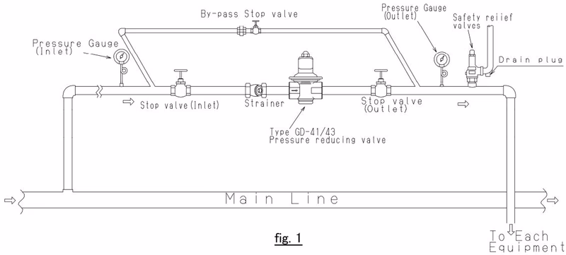
Installation Precautions
Many faults in pressure reducing valves are due to the existence of foreign materials. Before disassembling, verify that the strainer is not clogged (which decreases secondary pressure) and that the bypass valve is not leaking (which increases secondary pressure).
| Symptom | Possible Cause | Corrective Action |
|---|---|---|
| Reduced pressure is higher than set pressure | Damaged diaphragm. | Replace the diaphragm unit. |
| Foreign material pinched between valving disc and valve seat, or dents/scratches are seen on the seat. | Clean the assembly. If the disc or seat is damaged, replace the damaged part (or the valve casing). | |
| Poor seal of valve stem O-ring. | Replace the valve stem O-ring with a new one. | |
| Reduced pressure is lower than desired pressure / Fluid fails to flow | Valve stem O-ring is locked. | Replace the valve stem O-ring with a new one. |
| Valving element and valve seat are locked due to foreign material or damage. | Clean the disc and valve seat. Replace if damaged. | |
| Exterior Leakage | Loose cross-recessed pan head screws on the spring cover. | Retighten the screws evenly in a crisscross pattern. |
| Loose lower cap. | Retighten the lower cap. | |
| Broken O-ring on the lower cap. | Replace the O-ring for the cap with a new one. |
Disassembly Warning
When disassembling or checking, completely release the pressure from the valve and piping. Ensure the valve has cooled down. Residual pressure or hot drain may cause bodily injury. Replace O-rings upon every maintenance and coat them with fluorine grease before reassembly.
Periodic Replacement:
Explore similar products in our catalog