Cast Iron

TLV TATSU2 high-capacity air trap for highly viscous oil and condensate. Features a self-cleaning design, large orifice, and 1.0 MPaG maximum operating pressure.
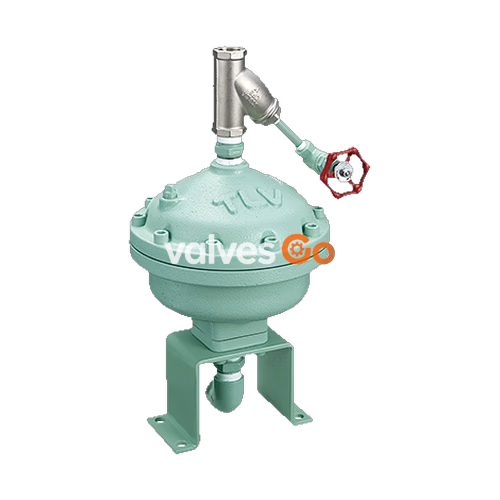
TLV TATSU2 is a large-capacity air trap designed to automatically drain highly viscous oil and condensate from compressed air systems. Recommended installations include receiver tanks, after coolers, and air mains. Its unique design allows self-cleaning of the trap interior during each discharge cycle, and the large size orifice eliminates problems due to dirt and oil accumulation.
| Model | TATSU2 |
|---|---|
| Connection | Screwed |
| Size (mm) | 25 |
| Maximum Operating Pressure (PMO) | 1.0 MPaG |
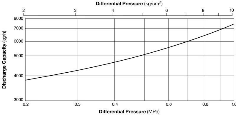
| Maximum Differential Pressure (ΔPMX) | 1.0 MPa |
| Minimum Differential Pressure | 0.2 MPa |
| Maximum Operating Temperature (TMO) | 80°C |
| Applicable Fluids* | Air |
PRESSURE SHELL DESIGN CONDITIONS (NOT OPERATING CONDITIONS)
Maximum Allowable Pressure (PMA): 1.0 MPaG Maximum Allowable Temperature (TMA): 150°C
| No. | Description | Material | JIS | ASTM/AISI* |
|---|---|---|---|---|
| 1 | Body | Cast Iron | FC250 | A126 Cl.B |
| 2 | Cover | Cast Iron | FC250 | A126 Cl.B |
| 3 | Outlet Union | Cast Iron | FC250 | A126 Cl.B |
| 4 | Float Cover | Polypropylene | PP | PP |
| 5 | Float | Stainless Steel | SUS316L | AISI316L |
| 6 | Float Holder | Polypropylene | PP | PP |
| 7 | Main Valve Seat | Stainless Steel | SUS303 | AISI303 |
| 8 | Piston | Stainless Steel | SUS303 | AISI303 |
| 9 | Pilot Valve Seat | Fluorine Resin | PTFE | PTFE |
| 10 | Main Valve | Nitrile Rubber/Stainl. Stl. | NBR/SUS304 | D2000BF/AISI304 |
| 11 | Pilot Valve | Nitrile Rubber/Stainl. Stl. | NBR/SUS303 | D2000BF/AISI303 |
| 12 | Cover Gasket | Fiber-Rubber Compound | — | — |
| 13 | Outlet Union Gasket | Fiber-Rubber Compound | — | — |
| 14 | Cover Bolt | Cr-Mo Steel | SMC435 | AISI4135 |
| 15 | Trap Support | Carbon Steel | SS400 | A6 |
| 16 | Outlet Elbow | Malleable Cast Iron | FCMB270 | A47 Gr.32510 |
| 17 | Nipple | Malleable Cast Iron | FCMB270 | A47 Gr.32510 |
| 18 | Y-Strainer | Cast Stainless Steel | — | A351 Gr.CF8 |
| 19 | Strainer Blow Valve | Malleable Cast Iron | FCMB270 | A47 Gr.32510 |
| 20 | Foundation Bolt/Nut | Carbon Steel | SS400 | A6 |
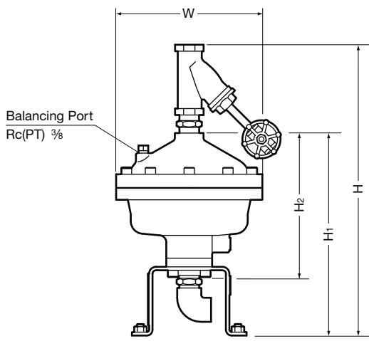
| Size | H** | H1** | H2 | φW | Weight (kg) |
|---|---|---|---|---|---|
| 25 | 495 | 354 | 250 | 255 | 21 |
Condensate and oil flow into and accumulate in the trap. 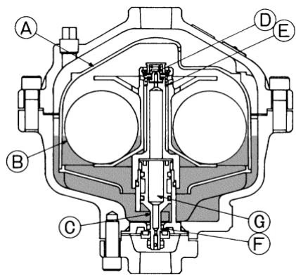
When the condensate level in the trap body rises to a certain point, the floats (B) rise. This, together with the help of the coil spring (E), lifts the float holder, causing the pilot valve (D) to open. 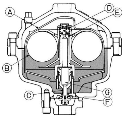
When the pilot valve (D) opens, compressed air (primary side) enters the pressure chamber (G) and pushes the piston (C) down, opening the main orifice (F) to discharge condensate and oil. The pressure inside the float cover (A) is lower than that outside, so the condensate outside the float cover discharges first, after which the condensate inside the float cover discharges. As the condensate inside the float cover discharges, some pressurized air will discharge with the condensate to flush out any oil or dirt in the trap and provide a self cleaning action. 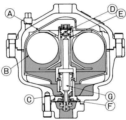
When the condensate has been discharged, the floats (B) fall, causing the pilot valve orifice (D) to close. When the pilot valve orifice (D) closes, the pressure in the pressure chamber (G) is released to the outlet and the piston (C) rises to close the main valve orifice (F). 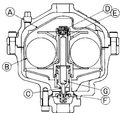
Note: In this manner, inflowing condensate is intermittently discharged.
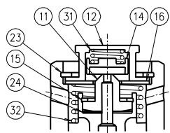
| No. | Name | No. | Name | No. | Name | No. | Name |
|---|---|---|---|---|---|---|---|
| 1 | Body | 12 | Spring Holder | 23 | Snap Ring | 34 | Elbow |
| 2 | Cover | 13 | Main Valve | 24 | Valve Seat Gasket | 35 | Mounting Base |
| 3 | Outlet Union | 14 | Pilot Valve | 25 | Cover Bolt | 36 | Anchor Bolt |
| 4 | Float Cover | 15 | Snap Ring | 26 | Outlet Union Bolt | 37 | Anchor Nut |
| 5 | Bottom Plate | 16 | Pilot Valve Support Plate | 27 | Castle Nut | 38 | Caution Faceplate |
| 6 | Piston Guide | 17 | Outlet Union Gasket | 28 | Split Pin | 39 | Caution Faceplate |
| 7 | Float | 18 | Cover Gasket | 29 | Spring Washer | 40 | Nameplate |
| 8 | Float Holder | 19 | Slide Ring | 30 | Balancing Line Plug | 41 | Y-Strainer |
| 9 | Main Valve Seat | 20 | Main Valve O-Ring | 31 | Sealing Spring | 42 | Pipe |
| 10 | Piston | 21 | Piston Guide O-Ring | 32 | Opening Spring | 43 | Globe Valve |
| 11 | Pilot Valve Seat | 22 | Piston O-Ring | 33 | Nipple |
WARNING
Install properly and DO NOT use this product outside the recommended operating pressure, temperature and other specification ranges. Improper use may result in such hazards as damage to the product or malfunctions which may lead to serious accidents.
This air trap is designed to automatically and intermittently discharge inflowing condensate. However, if the condensate completely fills the inlet path to the trap, air in the trap body will not be able to escape, preventing displacement by condensate, and thus preventing condensate from entering the trap. This phenomenon is called air binding. A pressure-balancing line installed between the trap cover and the dry portion of the receiver tank is used to prevent this phenomenon from occurring.
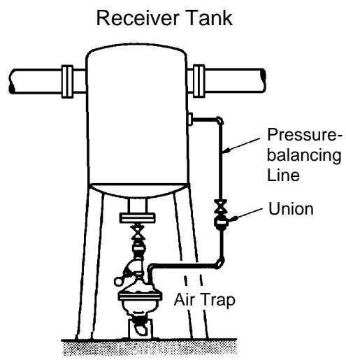
Note: Be sure to connect the pressure-balancing line to an area with the same pressure or to an air section downstream of the flow medium.
When the product fails to operate properly, use the following table to locate the cause and remedy.
| Problem | Cause | Remedy |
|---|---|---|
| No condensate is discharged (blocked) or discharge is poor | The pilot valve seat is clogged with scale | Clean parts |
| There is a build-up of scale between the piston and the main valve seat | Clean parts | |
| There is a build-up of rust or scale between the float holder and the piston guide | Clean parts | |
| The trap has the wrong number of floats (requires 4), or the floats are damaged or full of condensate | Inspect and replace if necessary | |
| The vent hole in the float cover is clogged with rust and scale | Clean parts | |
| The pressure-balancing line is clogged with rust and scale | Clean parts | |
| The opening spring is broken | Inspect and replace if necessary | |
| Air and/or condensate leaks from the outlet between discharge cycles (air leakage) | Scale has built up on the pilot valve seat or valve or the seating surfaces are scratched, crushed or worn | Clean or replace parts |
| Scale has built up on the main valve seat or main valve or the seating surfaces are scratched, crushed or worn | Clean or replace parts | |
| The trap is subjected to direct heavy vibration from the compressor | Inspect and anchor if necessary | |
| The sealing surfaces of an O-ring are scratched or damaged | Inspect and replace if necessary | |
| Air is blowing and the valve does not close (blowing) | There is a build-up of sticky scale between the float holder and the piston guide | Clean parts |
| The orifice of the piston is clogged with scale | Clean parts | |
| Scale has built up on the pilot valve seat | Clean parts | |
| The sealing spring is broken | Inspect and replace if necessary | |
| Air is leaking from a place other than the outlet | Gaskets are deteriorated or damaged | Replace with new gasket(s) |
| Improper tightening torques were used | Tighten to the proper torque |
Explore similar products in our catalog