Stainless Steel 304L

Armstrong 1/2/3/6-LD Series cast iron free floating lever liquid drainers feature an elliptical float and hemispherical valve for wide opening and tight shutoff.
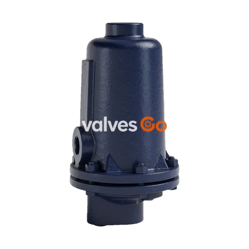
Armstrong 1/2/3/6-LD Series cast iron free floating lever liquid drainers use the same body, cap, leverage mechanism, valve, and seat as inverted bucket steam traps that have been proven in years of service. The elliptical float and high leverage allow the valve to open wide, providing sufficient capacity to support the size and weight of the drainer.
When liquid begins to fill the drainer body, the float rises, opening the discharge valve. The movement of the free lever is guided to achieve precise closure. The valve opening is wide enough to discharge liquid as quickly as it reaches the drainer. Therefore, sometimes the valve barely cracks from the seat.
The free lever mechanism features a hemispherical valve connected to a lever that hangs freely on two guide pins. There are no fixed pivots and no rigid guides. As a result, the attachments are loose. There is no critical alignment, and the lever and valve can move in all directions. Thus, the lever can move the valve to the seat in any alignment. As the valve approaches the seat, pressure pushes the rounded valve into the straight-edged orifice of the seat, sealing the line and achieving an air-tight shutoff.
| Model | Nominal Size | Max Allowable Pressure | Body Material | Connection Type |
|---|---|---|---|---|
| 1-LD | 15 mm (1/2") | 21 barg @ 93°C (300 psig @ 200°F) | ASTM A48 Class 30 Cast Iron | Threaded |
| 2-LD | 15 mm (1/2"), 20 mm (3/4") | 17 barg @ 232°C (250 psig @ 450°F) | ASTM A48 Class 30 Cast Iron | Threaded |
| 3-LD | 15 mm (1/2"), 20 mm (3/4"), 25 mm (1") | 17 barg @ 232°C (250 psig @ 450°F) | ASTM A48 Class 30 Cast Iron | Threaded |
| 6-LD | 40 mm (1-1/2"), 50 mm (2") | 17 barg @ 232°C (250 psig @ 450°F) | ASTM A48 Class 30 Cast Iron | Threaded |
Pipe Fitting: Before hooking up drainers, clean the pipes carefully after cutting and threading. To clear the pipes of dirt, pipe cuttings and other foreign objects, blow-down the drainer connected to the system at full pressure.
Strainers are necessary if there is a chance that scale and sediment can be carried to the drainer. Blow-Down Valve, "C" as shown in Figures 1 and 2 may also prove useful. Shut-off Valves and Unions should be installed so the drainer can be examined and/or serviced without shutting down the unit being drained by the drainer.
WARNING
Maximum operating pressure is stamped on the drainer. Do not exceed this pressure.
Operation:
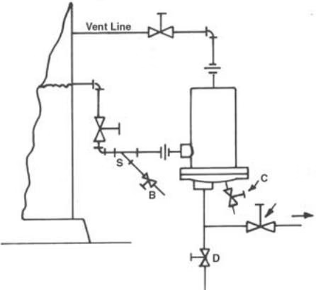 Figure 1. Installation of ball float drainer for medium or heavy loads. Strainer blow-down valve “B” and drainer blowdown valve “C” are optional. Discharge line valve “D” not required if drainer discharges water to ground.
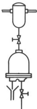 Figure 2. Installation of drainer when amount of liquid is small enough so liquid can flow to drainer countercurrent to gas displaced. Note: Drain line should be 3/4” minimum and kept as short as possible. A gate valve must be used.
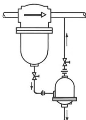 Figure 3. Installation of drainer for separator applications where back venting is necessary. Notice that the drainer is vented to the downstream side of the separator.
TIP
A regular schedule should be set-up for drainer testing and preventative maintenance. Drainer size and operating pressure determine how frequently drainers should be checked.
Drainers on normal industrial applications should be checked as follows:
Drainers on gas and other critical applications should be checked at the same time valves and other line equipment are inspected.
A mechanism less float, or pressure change assembly (PCA) consists of:
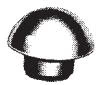 Valve
Valve
 Valve Seat
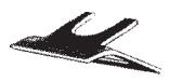 Valve Retainer
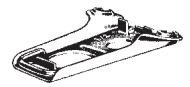 Valve Lever
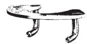 Guide Pin Assembly (With Screws)
Make sure that your parts are stamped with the orifice size required for your operating pressure. The orifice size (1/8” for example) is stamped on the valve seat, valve lever, and guide pin assembly. Parts with different orifice stampings should never be used together.
Armstrong valves and seats have been carefully lapped together and are furnished for installation as matched sets. Do not use a new seat with an old valve (or vise-versa). Pipe dope or lubricant is not required on valve seat threads. The joint is made, not by the threads, but by metal to metal contact at the ground end of the valve seat, as shown in Figure 1. Make sure seating area in cap is clean before screwing valve seat into position.
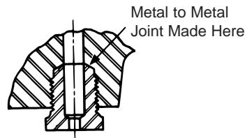 Figure 1 Important! Valve seat seal is made at point of contact indicated, not by threads.
The valve lever hooks over the guide pins. In a few sizes of traps, this part must be attached before the guide pin assembly is fastened into position. Fulcrums of levers are sheared at the Factory to obtain maximum opening pressure as well as maximum valve travel which ensures full capacity. Never tamper with height or position of fulcrums. Any change will adversely affect opening pressure, capacity, or both.
Pins always point away from adjoining gasket surface.
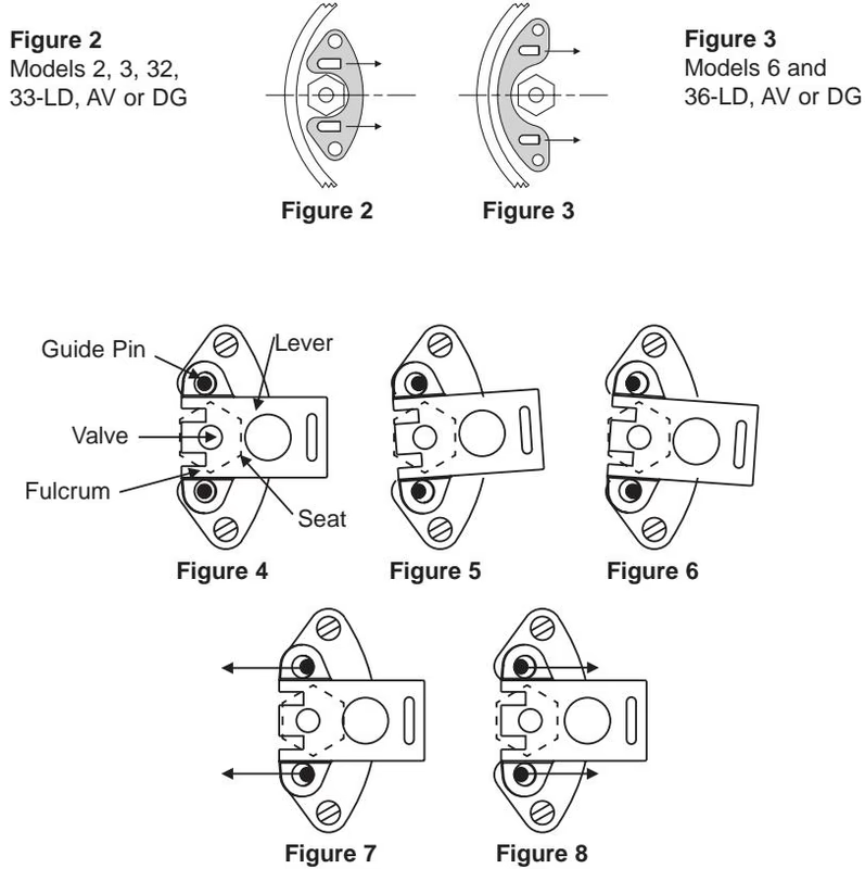
To check the alignment of guide pins, hold the lever and valve against the valve seat with the valve contacting its seat and the two fulcrum points resting on the face of the seat. When the lever is held in this position, the guide pins should be central in the guide pin holes. When correctly aligned, lever can be moved sideways the same distance to the right as to the left. Should the guide pins be out of line for any reason, they should be straightened so that they will be central in the guide pin holes.
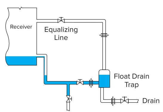 This is the best method for piping in a liquid drainer. The liquid drainer is below the receiver to allow the receiver to drain out completely, and the drainer is back vented. Notice there are no dips in the piping. However, if there were dips the drainer would operate just fine due to the back vent.
 For light loads only: The drain trap installed at side of a receiver, close to the floor. Water will rise to the broken line before the drain trap opens.
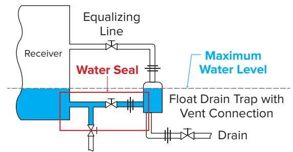
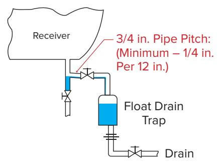 This piping method works because the liquid drainer is back vented. However, the liquid drainer is not below the receiver, so the receiver will hold a water level. This water level causes a water seal. But, since the liquid drainer is back vented, the water seal does not cause any issues.
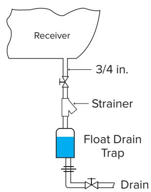
 As long as the strainer is regularly blown down: Installation with a strainer protecting the drain trap. A strainer can be used when a dirt pocket is absent as long as there is a regular blowdown schedule to clean the strainer screen.
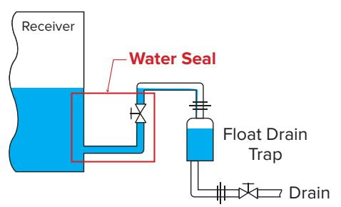
 Air will lock the drainer shut and prevent condensate from entering the drainer, because there is a water seal and there is no back vent/equalizing line.
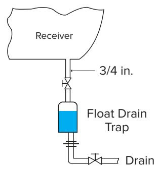 Installation is not recommended because of the dirt problem that can occur with a drain trap installed directly under the receiver.
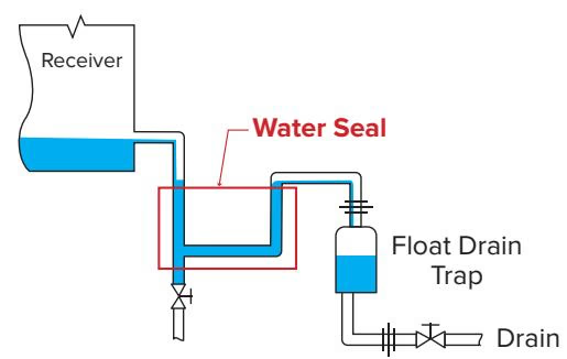 While this piping method will work, the absence of a dirt pocket will cause the internal seat orifice to eventually plug.
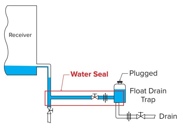 The float inside the liquid drainer causes the liquid drainer to hold a water level. This water level in the liquid drainer body causes a water seal. Without a back vent, the drainer will lock shut due to air lock.
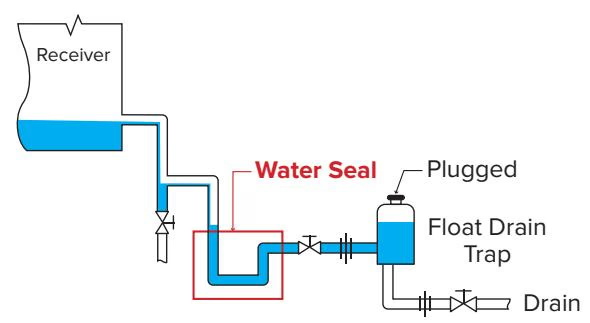 Air will lock the drainer shut and prevent condensate from entering the drainer, because there is a water seal and there is no back vent/equalizing line. Also, the side connection should not be used as the inlet if there is no back vent.
Explore similar products in our catalog