


PN16

TLV JH15S-21 high capacity cast steel float dynamic steam trap with free float pilot mechanism. Designed for large process heat exchangers, max 21 barg.
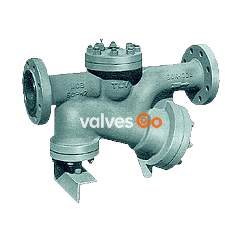
The TLV JH15S-21 is a high-capacity, cast steel, inline maintainable float dynamic steam trap featuring a free float and piston combination. Designed specifically for the discharge of high condensate flow rates, this product is ideal for use on large process heat exchangers, heaters, dryers, or other steam equipment where massive quantities of condensate are generated. The self-modulating free float pilot mechanism ensures discharge at near-to-steam temperatures, while the proven piston valve allows for "pulsing" discharge at high flow rates and intermittent discharge at low flow rates.

WARNING
NEVER apply direct heat to the float. The float may explode due to increased internal pressure, causing accidents leading to serious injury or damage to property and equipment.
| Model | JH15E-21, JH15M-21, JH15S-21 |
|---|---|
| Connection | Flanged |
| Size (DN) | 100 |
| Max. Operating Pressure (PMO) | 21 barg |
| Max. Differential Pressure (ΔPMX) | 21 bar |
| Min. Differential Pressure | 0.5 bar |
| Max. Operating Temperature (TMO) | 400 / 425 °C |
| Maximum Allowable Pressure (PMA) | 50 barg (Pressure shell design condition) |
Note: The minimum differential pressure is 0.05 MPa (0.5 bar). Do not use this product with a differential pressure less than this.
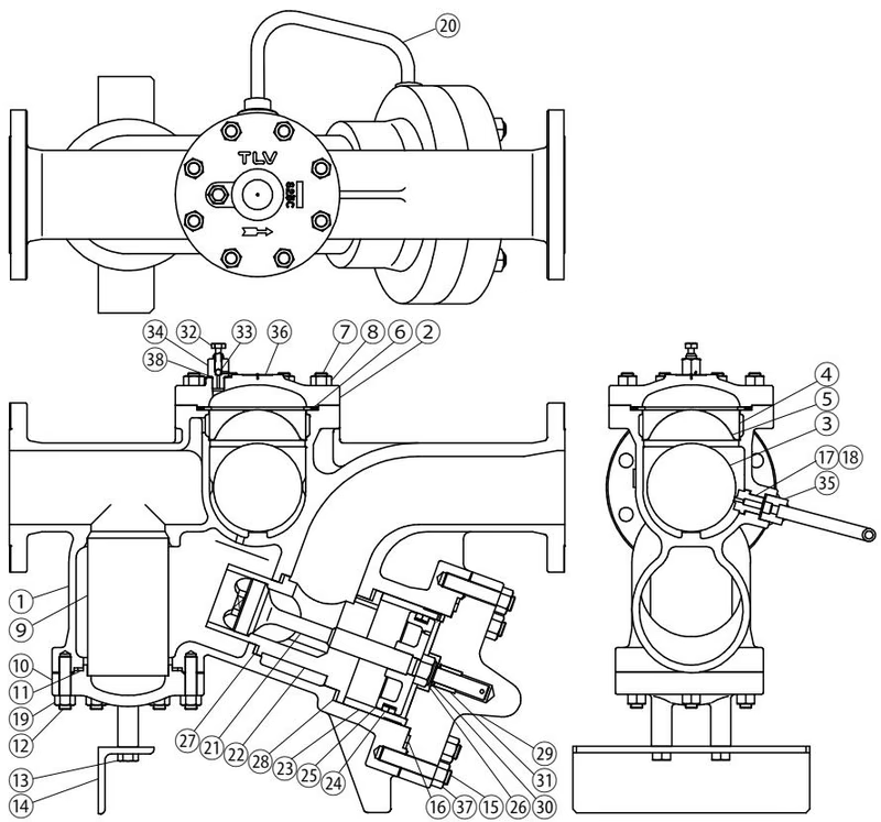
Key materials include:
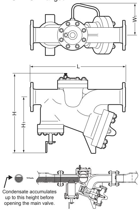
| Size (DN) | L (DIN PN25/40) | L (ASME 150RF) | L (ASME 300RF) | H | H1 | W1 | Weight (kg) |
|---|---|---|---|---|---|---|---|
| 100 | 750 mm | 766 mm | 792 mm | 635 mm | 440 mm | 250 mm | 171 (182) |
(Weight is for DIN PN 25/40. Value in parentheses is for ASME 300RF.)
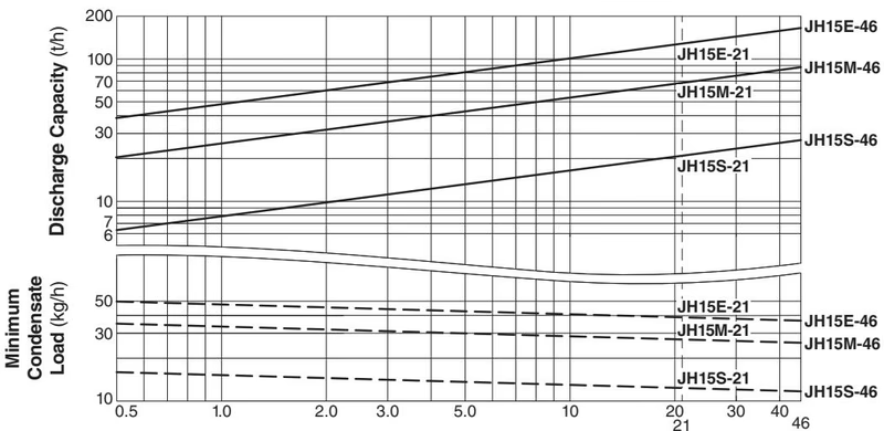
DANGER
DO NOT use this product under conditions that exceed maximum differential pressure, as condensate backup will occur!
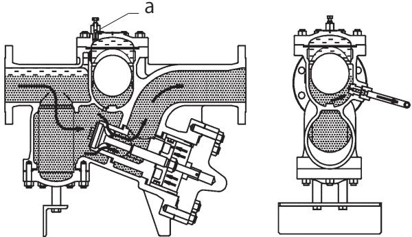
At start-up, air is discharged manually through operation of the air vent valve on the top of the cover. When condensate flows into the product, the float rises due to buoyancy and the condensate flows through the orifice into the cylinder, creating a secondary pressure there. This secondary pressure pushes the piston up, opening the main valve and discharging the condensate that is inside the product.
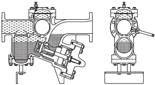
When condensate discharge is complete, the float falls, closing the orifice. When this happens, the secondary pressure in the cylinder escapes to the outlet through the tiny holes in the piston, causing the inlet pressure to push the main valve back down and closed. In this manner, condensate is intermittently discharged.
Firmly secure piping immediately before and after the product. During operation (opening/closing of the main valve), discharging condensate and return flow may cause vibration (strong shocks), which could lead to severe pipeline shaking.
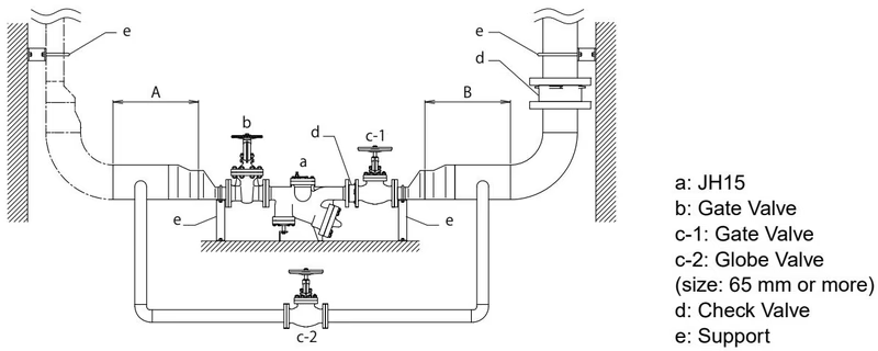
Inlet Horizontal Piping Length vs. Size:
| Length (m) | Size (mm) |
|---|---|
| 1.0 | 300 |
| 1.25 | 250 |
| 1.5 | 200 |
| 2.5 | 150 |
| 3.5 | 125 |
| 5.0 | 100 |
INFO
As a large amount of condensate is discharged at once, vibrations associated with operation occur. The vibration during operation can be reduced by ensuring the horizontal portion of the outlet pipe is of sufficient volume to accommodate the condensate load.
If the product fails to operate properly, use the following table to locate the cause and remedy.
| Problem | Cause | Remedy |
|---|---|---|
| No condensate is discharged (blocked) or discharge is poor | The float is damaged or filled with condensate | Replace with a new float |
| There is no inflow of condensate | Inspect and correct the piping | |
| The orifice opening or piping are clogged with rust and scale | Clean parts | |
| The trap operating pressure exceeds the maximum specified pressure or insufficient pressure differential | Compare specifications and actual operating conditions | |
| Air binding or steam-locking has occurred | Operate the lock release valve, perform a bypass blowdown or close the trap inlet valve and allow the trap to cool | |
| Steam is discharged or leaks from the outlet (blowing/steam leakage) | The piston or cylinder is damaged or the exhaust holes in the main valve stem have become enlarged | Replace with a new piston, cylinder or main valve |
| The piston or cylinder has a build-up of sticky scale | Clean parts | |
| The cylinder is installed in an incorrect orientation | Reinstall the piston with the correct orientation | |
| The small holes in the piston have become clogged | Clean parts | |
| The main valve has a build-up of sticky scale | Clean | |
| The main valve, cylinder or orifice is worn | Replace with new parts as required | |
| Steam is leaking from a place other than the outlet | Gasket deterioration or damage | Replace with new gasket(s) |
| Improper tightening torques were used | Tighten to the proper torque | |
| Float is frequently damaged | Water hammer has occurred | Study and correct the piping |




