Cast Iron

Spirax Sarco SCA series maintainable carbon steel inverted bucket steam traps with in-line connections and integral strainer. Suitable for up to 51 bar g and 400°C.
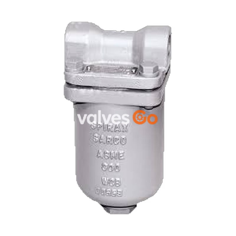
The Spirax Sarco SCA series are maintainable carbon steel inverted bucket steam traps with in-line connections. They are suitable for a wide range of pressures and incorporate an integral strainer. The product is available with material certification to EN 10204 3.1.B as standard (certification must be specified at the time of order).
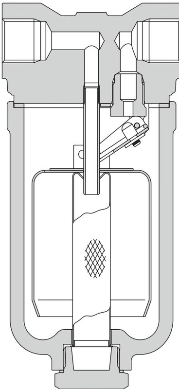
Maximum operating conditions depend on the orifice size. The SCA 30 product is verified safe for use under full vacuum conditions.
| Body design conditions | ANSI/ASME 300 (PN50) |
|---|---|
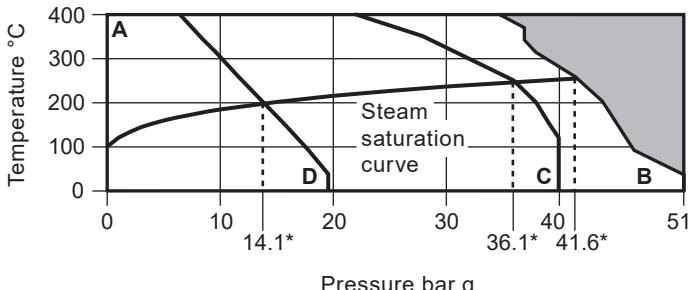
| PMA - Maximum allowable pressure | 51 bar g |
| TMA - Maximum allowable temperature | 400 °C |
| Designed for a maximum cold hydraulic test pressure of: | 78 bar g |
INFO
A - B: Flanged ANSI 300, screwed and socket weld. A - C: Flanged BS 4504 PN40 (ISO 7005.1). A - D: Flanged ANSI 150.
| Size | 3 bar | 5 bar | 11 bar | 15 bar | 30 bar | 40 bar |
|---|---|---|---|---|---|---|
| DN15 (1/2") | SCA3 | SCA5 | SCA11 | SCA15 | SCA30 | SCA40 |
| DN20 (3/4") | SCA3 | SCA5 | SCA11 | SCA15 | SCA30 | SCA40 |
| DN25 (1") | SCA3 | SCA5 | SCA11 | SCA15 | SCA30 | SCA40 |
The SCA15, SCA30 and SCA40 are available as standard and the SCA3, SCA5 and SCA11 to special request.
TIP
The pressure limit on the flange specified should be greater than the pressure limit of the internal mechanism.
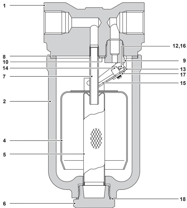
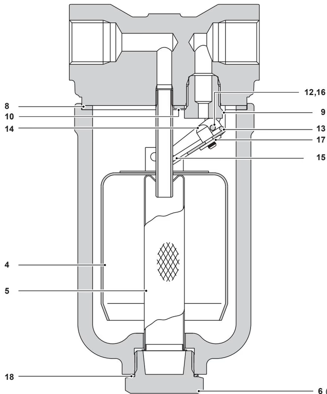
| No | Part | Material | Standard |
|---|---|---|---|
| 1 | Body | Carbon steel | ASTM A105 |
| 2 | Cover | Carbon steel | A216 WCB |
| 3* | Cover bolts | Steel | ASTM A193 Gr. B7 |
| 4 | Bucket | Stainless steel | AISI 304-2B |
| 5* | Screen | Stainless steel | AISI 304 |
| 6 | Strainer cap | Stainless steel | AISI 416 |
| 7 | Inlet tube | Stainless steel | AISI 304 |
| 8 | Cover gasket | Reinforced exfoliated graphite | - |
| 9 | Valve seat | Stainless steel | AISI 440C |
| 10 | Valve guide plate | Stainless steel | AISI 304-2B |
| 11* | Valve guide plate screws | Stainless steel | BS 6105 CI A2-70 |
| 12 | Hinge pin | Stainless steel | AISI 304 |
| 13 | Valve lever | Stainless steel | AISI 304-2B |
| 14* | Valve head | Stainless steel | AISI 420 |
| 15 | Spring pin | Stainless steel | AISI 304 |
| 16 | Washer | Stainless steel | AISI 304 |
| 17 | Starlock washer | Stainless steel | AISI 301 |
| 18 | 'S' type gasket | Stainless steel | AISI 304 |
* Note: Items 3 and 11 are not illustrated.
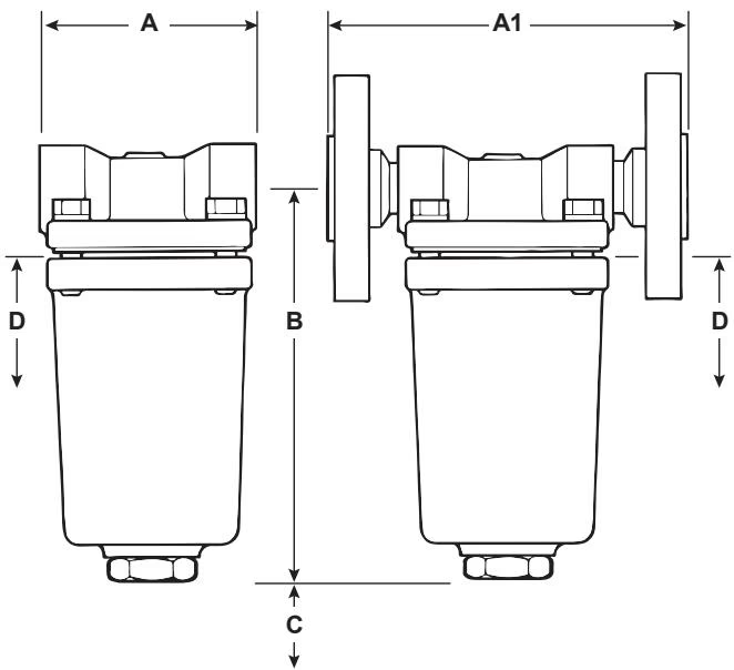
Dimensions (approximate) in mm:
| Size | Screwed / SW (A) | PN40 (A1) | ANSI 150 (A1) | ANSI 300 (A1) | B | Withdrawal C | Withdrawal D |
|---|---|---|---|---|---|---|---|
| DN15 (1/2") | 90 | 150 | 150 | 150 | 167 | 100 | 110 |
| DN20 (3/4") | 90 | 150 | 150 | 150 | 167 | 100 | 110 |
| DN25 (1") | 165 | 160 | 160 | 160 | 167 | 100 | 110 |
Weights (approximate) in kg:
| Size | Screwed / SW | PN40 | ANSI 150 | ANSI 300 |
|---|---|---|---|---|
| DN15 (1/2") | 3.0 | 4.7 | 4.6 | 5.0 |
| DN20 (3/4") | 3.0 | 5.3 | 5.0 | 5.8 |
| DN25 (1") | 3.5 | 6.0 | 5.7 | 6.5 |
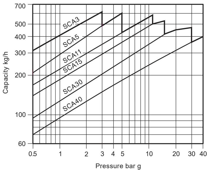
Capacities are in accordance with ISO 7842.
WARNING
The cover gasket contains a thin stainless steel support ring which may cause physical injury if it is not handled and disposed of carefully.
Installation: The trap must be installed with the body upright so that the bucket is rising and falling vertically. The inlet and outlet connections should be in a horizontal plane, with the trap installed below the drain point so that a water seal can be maintained around the open end of the bucket.
How to fit valve and seat assembly: Isolate the inverted bucket steam trap, remove the body by undoing the cover bolts. Remove the complete bucket assembly by undoing the two screws. Remove the valve seat. Screw in the new valve seat to the torque figures shown, using a little jointing paste on the threads and making sure that joint faces are clean. Fix the new bucket assembly in position by using new screws which are supplied, centralise the valve to the orifice and tighten screws to the torque figures shown. Using new gaskets, refit the body to the torque figures shown.
| Available Spares | Item Numbers |
|---|---|
| Internal set (state pressure range) | 4, 8, 9, 10, 11 (2 off)*, 12, 13, 14, 15, 16 (2 off), 17 |
| Strainer set | 5, 18 |
| Cover and strainer gasket (packet of three) | 8, 18 |
* Note: Item 11 (valve guide plate screws) are not shown.
| Item | Part | A/F (mm) | Thread | Torque (N m) |
|---|---|---|---|---|
| 3* | Cover bolts | 14 | M10 | 40 - 45 |
| 6 | Strainer cap | 32 | M28 | 170 - 190 |
| 9 | Valve seat | 17 | M16 | 35 - 40 |
| 11* | Valve guide plate screws | Posidrive | M4 x 6 | 2.5 - 3.0 |
Explore similar products in our catalog