


PN25

The Armstrong GD-45 is a compact, direct-acting pressure reducing valve for steam, air, and non-corrosive gases. Features a ductile iron body, 10:1 turndown ratio, and ANSI Class IV shutoff.
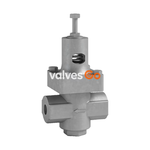
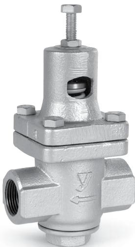
The Armstrong GD-45 is a compact, high-performance, direct-acting pressure reducing valve designed for steam, air, and non-corrosive gas service. Inexpensive to buy and use, it is ideal for moderate flow applications that do not justify the higher cost of pilot-controlled valves. The GD-45 is well-suited for laundry and dry-cleaning equipment, hospital equipment, tire molds, humidifiers, small heaters, and applications in food processing. It provides tight, quick, and easy installation.
Quick, easy installation
Simple selection
Long life and easy maintenance
| Service | Inlet Pressure psig (barg) | Reduced Pressure psig (barg) | Minimum Differential psig (barg) | Maximum Temperature °F (°C) | Body Material | Valve/Seat Material | Bellows Material |
|---|---|---|---|---|---|---|---|
| Steam, Air, Non-Corrosive Gases | 15 - 300 (1 - 20) | 3 - 15 (0.21 - 1.0) Yellow 7 - 60 (0.5 - 4.0) Blue 50 - 140 (3.4 - 9.6) Green | 7 (0.48) | 450 (232) | ASTM A536 Ductile Iron | Hardened Stainless Steel AISI 420 | Phosphor Bronze ASTM B103 |
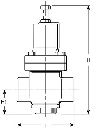
| Symbol | 1/2" (15 mm) | 3/4" (20 mm) | 1" (25 mm) |
|---|---|---|---|
| L | 4-3/8" (111 mm) | 4-3/8" (111 mm) | 4-3/8" (111 mm) |
| H1 | 1-7/8" (47 mm) | 1-7/8" (47 mm) | 1-7/8" (47 mm) |
| H | 8-1/2" (216 mm) | 8-1/2" (216 mm) | 8-1/2" (216 mm) |
| Weight | 7 lb (3.2 kg) | 7 lb (3.2 kg) | 7 lb (3.2 kg) |
| Cv | 1.3 | 1.5 | 2.5 |
INFO
GD-45 capacities cannot be determined with a formula—consult the capacity tables below. For air capacities in scfm, multiply steam capacities (lb/hr) by 0.36. For air capacities in m³/hr, multiply steam capacities (kg/hr) by 1.35. Maximum pressure reduction ratio is 10:1.
| Inlet | Outlet | 1/2" | 3/4" | 1" | Inlet | Outlet | 15 mm | 20 mm | 25 mm |
|---|---|---|---|---|---|---|---|---|---|
| psig | psig | lb/hr | lb/hr | lb/hr | barg | barg | kg/hr | kg/hr | kg/hr |
| Cv Factor | 1.3 | 1.5 | 2.5 | Cv Factor | 1.3 | 1.5 | 2.5 | ||
| 15 | 7 | 49 | 56 | 92 | 1.0 | 0.5 | 22 | 25 | 42 |
| 20 | 13 | 53 | 61 | 105 | 1.4 | 0.9 | 24 | 28 | 48 |
| 20 | 7 | 42 | 55 | 63 | 1.4 | 0.5 | 19 | 25 | 35 |
| 30 | 23 | 62 | 71 | 112 | 2.0 | 1.6 | 28 | 32 | 51 |
| 30 | 15 | 53 | 60 | 101 | 2.0 | 1.0 | 24 | 27 | 46 |
| 30 | 3 | 33 | 40 | 60 | 2.0 | 0.2 | 15 | 18 | 27 |
| 40 | 32 | 99 | 121 | 187 | 2.8 | 2.2 | 45 | 55 | 85 |
| 40 | 20 | 79 | 97 | 159 | 2.8 | 1.4 | 36 | 44 | 72 |
| 40 | 4 | 40 | 55 | 77 | 2.8 | 0.3 | 18 | 25 | 35 |
| 50 | 40 | 130 | 143 | 242 | 3.4 | 2.8 | 59 | 65 | 110 |
| 50 | 20 | 99 | 115 | 187 | 3.4 | 1.4 | 45 | 52 | 85 |
| 50 | 5 | 48 | 62 | 88 | 3.4 | 0.3 | 22 | 28 | 40 |
| 60 | 48 | 137 | 154 | 265 | 4.0 | 3.3 | 62 | 70 | 120 |
| 60 | 40 | 150 | 165 | 289 | 4.0 | 2.8 | 68 | 75 | 131 |
| 60 | 18 | 90 | 104 | 170 | 4.0 | 1.2 | 41 | 47 | 77 |
| 60 | 6 | 55 | 73 | 99 | 4.0 | 0.4 | 25 | 33 | 45 |
| 80 | 64 | 176 | 205 | 342 | 5.5 | 4.4 | 80 | 93 | 155 |
| 80 | 54 | 187 | 225 | 353 | 5.5 | 3.7 | 85 | 102 | 160 |
| 80 | 23 | 121 | 137 | 220 | 5.5 | 1.6 | 55 | 62 | 100 |
| 80 | 8 | 60 | 77 | 108 | 5.5 | 0.5 | 27 | 35 | 49 |
| 100 | 80 | 203 | 242 | 397 | 6.9 | 5.5 | 92 | 110 | 180 |
| 100 | 66 | 225 | 262 | 437 | 6.9 | 4.5 | 102 | 119 | 198 |
| 100 | 40 | 198 | 231 | 375 | 6.9 | 2.8 | 90 | 105 | 170 |
| 100 | 10 | 68 | 79 | 132 | 6.9 | 0.7 | 31 | 36 | 60 |
| 120 | 96 | 231 | 276 | 452 | 8.3 | 6.6 | 105 | 125 | 205 |
| 120 | 70 | 276 | 311 | 518 | 8.3 | 4.8 | 125 | 141 | 235 |
| 120 | 45 | 240 | 267 | 450 | 8.3 | 3.1 | 109 | 121 | 204 |
| 120 | 12 | 110 | 121 | 198 | 8.3 | 0.8 | 50 | 55 | 90 |
| 150 | 120 | 287 | 333 | 551 | 10.3 | 8.3 | 130 | 151 | 250 |
| 150 | 85 | 364 | 421 | 705 | 10.3 | 5.9 | 165 | 191 | 320 |
| 150 | 55 | 298 | 353 | 595 | 10.3 | 3.8 | 135 | 160 | 270 |
| 150 | 15 | 132 | 165 | 254 | 10.3 | 1.0 | 60 | 75 | 115 |
| 180 | 140 | 408 | 485 | 794 | 12.4 | 9.7 | 185 | 220 | 360 |
| 180 | 115 | 430 | 507 | 860 | 12.4 | 8.0 | 195 | 230 | 390 |
| 180 | 70 | 386 | 430 | 739 | 12.4 | 4.8 | 175 | 195 | 335 |
| 180 | 18 | 165 | 187 | 309 | 12.4 | 1.2 | 75 | 85 | 140 |
| 200 | 140 | 461 | 518 | 871 | 13.8 | 9.7 | 209 | 235 | 395 |
| 200 | 115 | 474 | 540 | 904 | 13.8 | 8.0 | 215 | 245 | 410 |
| 200 | 80 | 430 | 496 | 827 | 13.8 | 5.5 | 195 | 225 | 375 |
| 200 | 20 | 209 | 242 | 386 | 13.8 | 1.4 | 95 | 110 | 175 |
| 225 | 140 | 485 | 573 | 948 | 15.5 | 9.7 | 220 | 260 | 430 |
| 225 | 115 | 496 | 584 | 961 | 15.5 | 8.0 | 225 | 265 | 436 |
| 225 | 85 | 463 | 540 | 904 | 15.5 | 5.9 | 210 | 245 | 410 |
| 225 | 23 | 254 | 298 | 496 | 15.5 | 1.6 | 115 | 135 | 225 |
| 250 | 140 | 525 | 606 | 1014 | 17.2 | 9.7 | 238 | 275 | 460 |
| 250 | 120 | 551 | 584 | 1038 | 17.2 | 8.3 | 250 | 265 | 471 |
| 250 | 70 | 463 | 529 | 893 | 17.2 | 4.8 | 210 | 240 | 405 |
| 250 | 25 | 276 | 320 | 529 | 17.2 | 1.7 | 125 | 145 | 240 |
| 300 | 140 | 528 | 616 | 1023 | 20.0 | 9.7 | 240 | 280 | 465 |
| 300 | 120 | 551 | 627 | 1038 | 20.0 | 8.3 | 250 | 285 | 477 |
| 300 | 70 | 484 | 550 | 913 | 20.0 | 4.8 | 220 | 250 | 415 |
| 300 | 30 | 319 | 352 | 583 | 20.0 | 2.0 | 145 | 160 | 265 |
Recommended Accessories
WARNING
Do not install quick opening or closing valves downstream of the PRV.
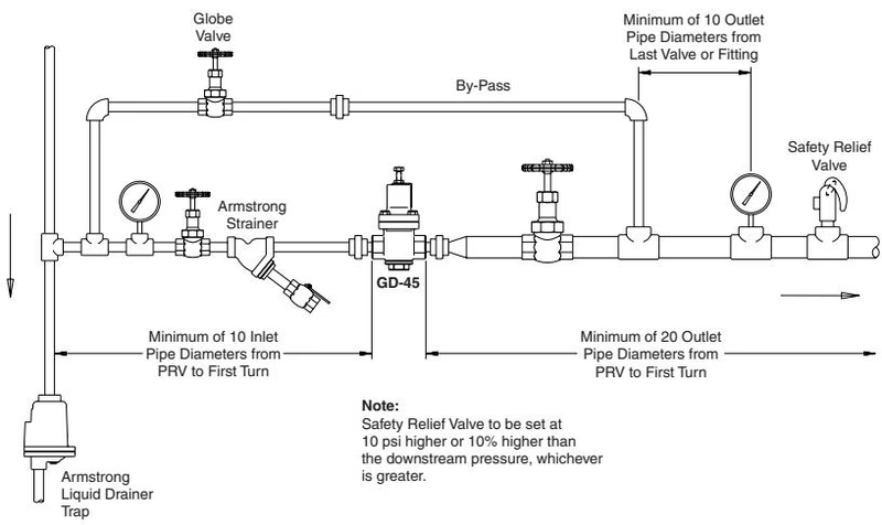
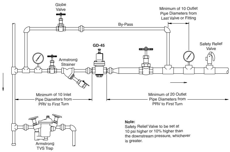
Improper adjustment of the pressure reducing valve may cause hunting, scale problems, water hammer, etc., and damage to the valve itself. Damaged pressure gauges, leakage or opening of a bypass valve, or clogging of an inlet strainer may cause problems similar to that of a malfunctioning reducing valve. Adjust the valve as follows:
| Problem | Causes | Solutions |
|---|---|---|
| The desired pressure cannot be obtained. | The inlet pressure is too low or high. | Change the pressure to the appropriate level. |
| The sensing port of the outlet pressure is clogged with foreign matter. | Disassemble and clean the sensing port. | |
| The valve size is smaller than what is required. | Change the valve size to the appropriate one. | |
| The adjustment is not appropriate. | Readjust according to the adjustment procedure. (See start-up procedure) | |
| The inlet strainer is clogged by foreign substance. | Disassemble and clean the strainer. | |
| The pressure gauge is not functioning properly. | Replace the pressure gauge. | |
| The outlet pressure rises higher than the specified pressure | The valve or valve seat is contaminated by foreign substance. | Disassemble and clean the valve or the seat. |
| The by-pass valve is leaking. | Repair or replace the by-pass valve. | |
| Abnormal noise is heard. | The reducing ratio is excessively large. | Reduce pressure by staging with second PRV. |
| Water hammer (for steam service). | Install a steam trap at the reducing valve inlet. | |
| There is a fast closing valve near the PRV. | Provide as long a distance as possible between the two valves. |
DANGER
Eliminate pressure from inside the valve. Make sure the valve is completely free from pressure before proceeding.
TIP
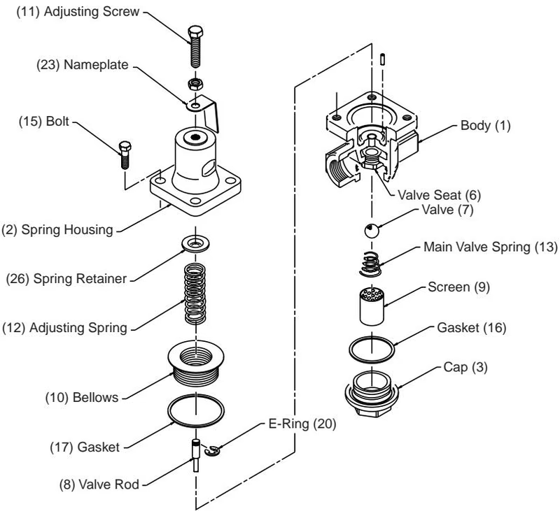
Replace all gaskets where disassembly is required.
Explore similar products in our catalog



