


PN25

Yoshitake GD-41G direct type pressure reducing valve for air, carbon dioxide, nitrogen, and steam. Features stainless steel wetted parts and PTFE-covered diaphragm.
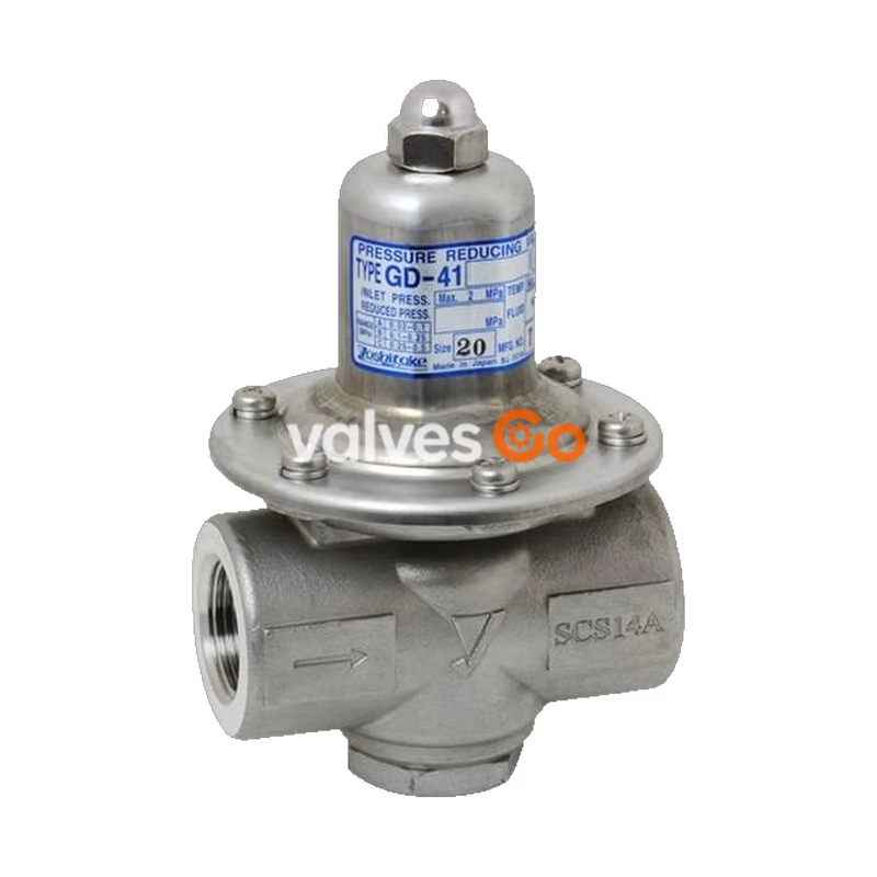
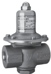
The Yoshitake GD-41G and GD-43G are direct type pressure reducing valves designed for air, carbon dioxide gas, nitrogen gas, and steam for washing or sterilization. They feature a space-saving design and use stainless steel (SCS14A and SUS316) for wetted parts to enhance corrosion resistance.
| Model | GD-41G | GD-43G-10 | GD-43G-20 |
|---|---|---|---|
| Application | Air, Carbon dioxide gas, Nitrogen gas / Steam for washing or sterilization | ||
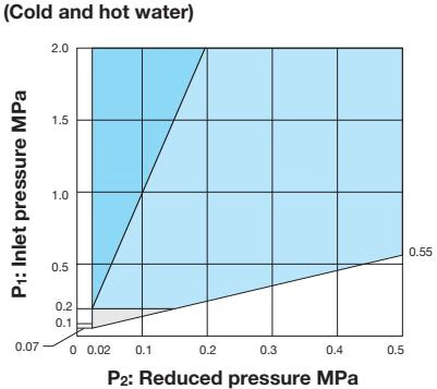
| Inlet pressure | 0.07-2.0 MPa (0.2 MPa or less for steam for washing or sterilization) | ||
| Reduced pressure | (A) Yellow spring: 0.02-0.1 MPa (B) Red spring: 0.1-0.25 MPa (C) Black spring: 0.25-0.5 MPa | ||
| Minimum differential pressure | 0.05 MPa | ||
| Maximum pressure reduction ratio | 20:1 | ||
| Fluid temperature | 5-90°C (The maximum temperature of steam for washing or sterilization is 130°C. Allow an interval of at least four hours between steam flows.) | ||
| Body Material | Cast Stainless steel (SCS14A) | ||
| Valve disc Material | Special synthetic rubber (special FKM) | ||
| Diaphragm Material | Heat-resistant synthetic rubber and PTFE (PTFE applied to wetted face) | ||
| Connection | JIS Rc screwed | JIS 10K FF flanged | JIS 20K RF flanged |
Notes
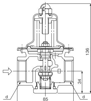
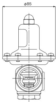
| Nominal size | d | Weight (kg) |
|---|---|---|
| 15A | Rc 1/2 | 1.2 |
| 20A | Rc 3/4 | 1.1 |
| 25A | Rc 1 | 1.0 |
All dimensions are same except connection size.
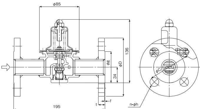
| Nominal Size | D | C | g | t | f | n-h | Weight (kg) |
|---|---|---|---|---|---|---|---|
| 15A | 95 | 70 | 51 | 14 (12) | 1 | 4-15 | 2.8 (2.6) |
| 20A | 100 | 75 | 56 | 16 (14) | 1 | 4-15 | 3.0 (2.9) |
| 25A | 125 | 90 | 67 | 16 (14) | 1 | 4-19 | 4.0 (3.7) |
The values in parentheses are the weights of the GD-43G-10. All dimensions are same except flange size.
| Set pressure | Offset pressure |
|---|---|
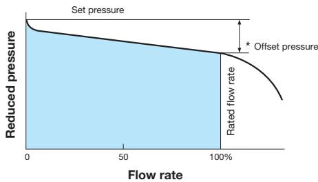
| 0.2 MPa or less | Within 0.05 MPa |
| More than 0.2 MPa | Within 0.08 MPa |
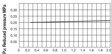
This chart shows variation in reduced pressure when the inlet pressure of 0.25 MPa is changed to 2.0 MPa while the reduced pressure is set at 0.20 MPa.
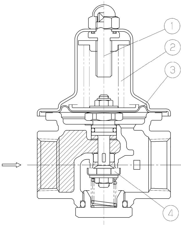
If the adjusting screw is turned right, the diaphragm will be depressed with an adjusting spring and Disc connected with spindle will open. The fluid which flowed in from the inlet side carries out the action which pushes up the diaphragm through a sensing hole at the same time it flows into outlet side through the Disc upper part. When the stop valve at the outlet side is closed, the load which pushes up the diaphragm increases, the load of an adjusting spring is overcome, and the Disc is closed.
If the stop valve at the outlet side is opened gradually, the load which pushes up the diaphragm will decrease, the load of an adjusting spring will be overcome, the Disc will be opened, and fluid will flow into the outlet side. The fluid which flowed into the outlet side through a sensing hole carries out the action which pushes up the diaphragm, maintains the balance with an adjusting spring load, adjusts the Disc opening, and keeps outlet side pressure constant.
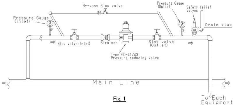
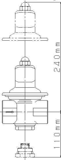
Precautions during installation
| Symptom | Possible Cause | Corrective Action |
|---|---|---|
| I. Reduced pressure is higher than set pressure | 1. Damaged diaphragm | 1. Replace the diaphragm unit |
| 2. Foreign material pinched between valving Disc and valve seat. Dents or scratches are seen on the valving element P or valve seat. | 2. Clean the assembly. If the Disc is damaged, replace it. If the valve seat section is damaged, replace the valve casing. | |
| 3. Poor seal of valve stem O ring | 3. Replace valve stem O ring with a new one. | |
| II. Reduced pressure is lower than the desired pressure. Fluid fails to flow. | 4. Valve stem O ring is locked. | 4. Replace valve stem O ring with a new one. |
| 5. Valving element P and valve seat is locked. | 5. Clean Disc and valve seat section. If damaged, replace the respective parts. | |
| III. Leakage | 6. Loosen cross recessed pan head screw | 6. Tighten cross recessed pan head screw. |
| 7. Loosen cap | 7. Tighten lower cap. | |
| 8. Broken O ring for cap. | 8. Replace O ring for cap with a new one. |
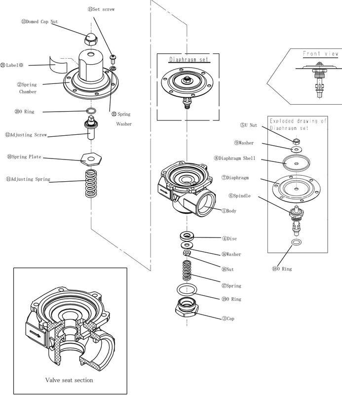
| Component | Part number | Replacement interval |
|---|---|---|
| Diaphragm set | 5, 6, 7, 8, 9, 18 | 3 years |
| Disc | 4 | 3 years |
| O Ring | 19, 20 | 3 years |
Yoshitake Control Valves / Pressure Reducing Valves
GP, GD, and CP series for stable pressure reduction and control in steam, water, and air systems.
Explore similar products in our catalog



