


PN25

Yoshitake GD-400 and GD-400SS pilot-operated diaphragm pressure reducing valves for air and nitrogen gas. Features a 400:1 maximum reduction ratio and external sensing.
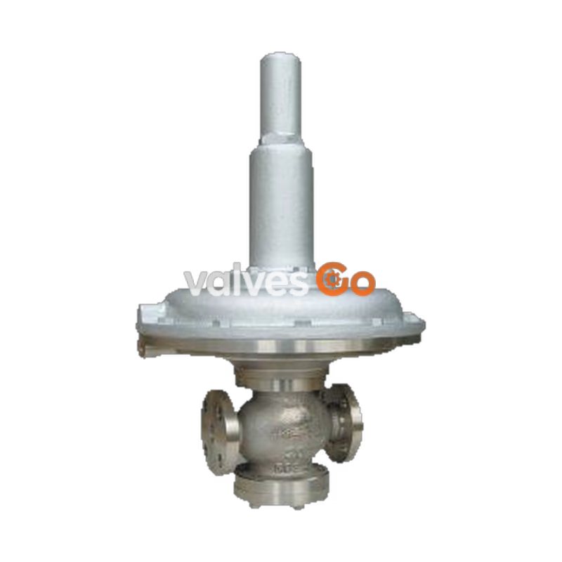
The Yoshitake GD-400 and GD-400SS are pilot-operated diaphragm pressure reducing valves designed for air and nitrogen gas applications. Featuring a pressure balance structure, these valves maintain a constant reduced pressure regardless of inlet pressure fluctuations. With a maximum pressure reduction ratio of 400:1 and a large pressure sensing area diaphragm, they offer highly accurate set pressure control over a wide range of operating conditions. The GD-400 features a cast iron body, while the GD-400SS is constructed from cast stainless steel (SCS14) for enhanced corrosion resistance.
| Model | GD-400 | GD-400SS |
|---|---|---|
| Nominal size | 15-50A | 15-50A |
| Application | Air, Nitrogen gas *1 | Air, Nitrogen gas *1 |
| Inlet pressure | 2.5-400 kPa | 2.5-400 kPa |
| Reduced pressure | (A) 0.5-1.4 kPa (B) 1.2-3.3 kPa (C) 3.0-8.0 kPa (D) 7.0-20 kPa | (A) 0.5-1.4 kPa (B) 1.2-3.3 kPa (C) 3.0-8.0 kPa (D) 7.0-20 kPa |
| Working temperature | 5-60°C *3 | 5-60°C *3 |
| Minimum differential pressure | 2.0 kPa | 2.0 kPa |
| Maximum reduction ratio | 400:1 | 400:1 |
| Detection method | External sensing *2 | External sensing *2 |
| Min adjustable flow rate | 15-25A: 1.2 m³/h (standard condition) 32-50A: 10.0 m³/h (standard condition) | 15-25A: 1.2 m³/h (standard condition) 32-50A: 10.0 m³/h (standard condition) |
| Body Material | Cast iron | Cast stainless steel (SCS14) |
| Valve / Seat / Spindle | Stainless steel | Stainless steel |
| Disc / Diaphragm | NBR *3 | NBR *3 |
| Connection | JIS 10K FF Flanged | JIS 10K FF Flanged |
Notes
*1 Please contact us when using for other fluids. *2 A conduit (φ8-2 m) and a joint for external sensing are included for GD-400. For GD-400SS, please prepare one at your end. *3 Available with FKM type (Operating temperature: 5~90 °C). Use on a compressed air system with dry air from oil-free compressors may cause deterioration of rubber parts in a very short time (ozone crack). Please consult with us before such installation.
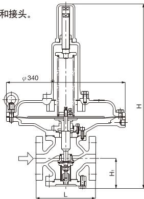
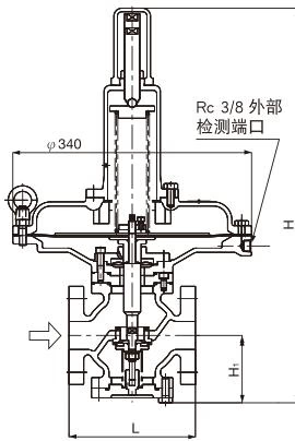
| Nominal size | L (mm) | H1 (mm) | H (mm) | Weight (kg) |
|---|---|---|---|---|
| 15A | 166 | 86 | 526 | 29.0 (32.0) |
| 20A | 170 | 86 | 526 | 29.0 (32.0) |
| 25A | 170 | 86 | 526 | 30.0 (33.0) |
| 32A | 180 | 96 | 561 | 32.0 (34.0) |
| 40A | 180 | 96 | 561 | 32.0 (34.0) |
| 50A | 180 | 101 | 561 | 33.0 (35.0) |
The values in parentheses are the weights of the GD-400SS.
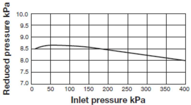
This chart shows variation in reduced pressure when the inlet pressure of 400 kPa is changed to 10 kPa while the reduced pressure is set at 8.0 kPa.
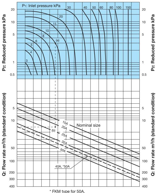
Example: When selecting the nominal size of a pressure reducing valve whose inlet pressure (P1), reduced pressure (P2), and flow rate are 10 kPa, 3 kPa, and 15 m³/h (standard condition), respectively, first find the intersection point (a) of the inlet pressure of 10 kPa and the reduced pressure of 3 kPa. Trace down vertically from this intersection point to find intersection point (b) with the flow rate of 15 m³/h (standard condition). Since intersection point (b) lies between nominal sizes 20A and 25A, select the larger one, 25A. Set the safety factor at 80 to 90%.
| Nominal Size | 15A | 20A | 25A | 32A | 40A | 50A |
|---|---|---|---|---|---|---|
| GD-400 | 1.5 | 2.0 | 3.0 | 5.0 | 6.0 | 8.0 [6.5] |
| GD-400SS | 1.5 | 2.0 | 3.0 | 5.0 | 6.0 [5.5] | 7.5 [6.0] |
[ ] indicates FKM Type.
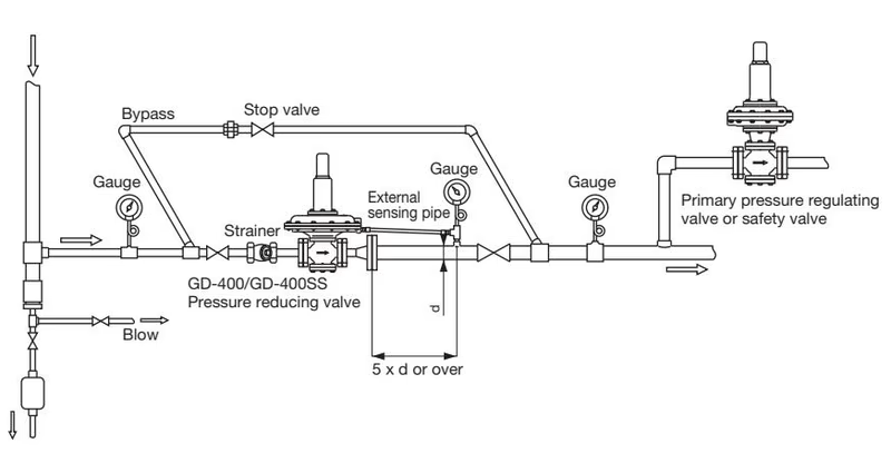
Installation Precautions
When performing a pressure test or airtight test after connection to the piping, apply the air test pressure specified below. If pressure beyond the specified air test pressure is applied, internal parts may be damaged.
| Airtight test | Pressure |
|---|---|
| Inlet pressure | 400 kPa or less |
| Reduced pressure (A) | 1.8 kPa or less |
| Reduced pressure (B) | 4.2 kPa or less |
| Reduced pressure (C) | 10 kPa or less |
| Reduced pressure (D) | 25 kPa or less |
Be aware of foreign materials in the piping since many faults in the pressure reducing valve are caused by the existence of foreign objects. A clogged strainer will decrease the outlet pressure, and a leaking bypass pipe will increase the outlet pressure.
| Parts | Replacement interval |
|---|---|
| Diaphragm | 3 years |
| Balance diaphragm | 3 years |
| Disc | 3 years |
| O-ring | 3 years |
| Problem | Presumable cause | Corrective action |
|---|---|---|
| I. Reduced pressure exceeds prescribed value. | 1. Leakage from the stop valve on bypass pipe. 2. External sensing pipe tube is not connected. 3. Needle valve is clogged by foreign materials. 4. Foreign object pinched between disc and valve seat. Damage to disc and/or valve seat. 5. Loosened hexagon socket head cap bolt and/or locknut. 6. Damaged diaphragm. 7. Damaged balance diaphragm. | 1. Close the stop valve. If leakage continues, replace the stop valve. 2. Connect the external sensing pipe. 3. Purge the foreign materials from needle valve. 4. Remove the foreign object. Replace the disc if damaged. If the seat is damaged, consult us. 5. Tighten hexagon socket head bolt and locknut. 6. Replace diaphragm. 7. Replace balance diaphragm. |
| II. Reduced pressure does not reach prescribed value. Or, fluid fails to flow. | 1. Strainer at inlet is clogged. 2. Needle valve is clogged by foreign materials. 3. Foreign object pinched between diaphragm shell and slide of top guide. | 1. Clean the screen of the strainer. 2. Remove foreign material from needle valve. 3. Remove foreign objects from diaphragm shell and slide of top guide. |
| III. External leakage | 1. Needle valve is clogged by foreign materials. 2. Loosened hexagon head bolt of bottom cover, or damaged O-ring. 3. Loosened hexagon head bolt on top diaphragm case. 4. Damaged diaphragm. | 1. Remove foreign material from needle valve. 2. Tighten hexagon head bolt on bottom cover or replace O-ring. 3. Tighten hexagon head bolt on top diaphragm case. 4. Replace diaphragm. |
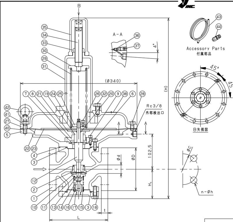
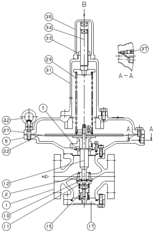
| No. | Name of Parts | Material | No. | Name of Parts | Material |
|---|---|---|---|---|---|
| 1 | Body | Cast Iron | 23 | Top Dia. Plate | Carbon Steel |
| 2 | Valve Seat | Stainless Steel | 24 | Washer | Steel |
| 3 | O Ring | NBR | 25 | Nut | Stainless Steel |
| 4 | O Ring | NBR | 26 | Bolt | Stainless Steel |
| 5 | Bottom Dia. Case | Cast Iron | 27 | Top Dia. Case | Cast Iron |
| 6 | Bolt | Stainless Steel | 28 | Bolt | Steel |
| 7 | Balance Diaphragm | NBR | 29 | Spring | Piano Wire |
| 8 | Top Guide | Stainless Steel | 30 | Spring Plate | Cast Iron |
| 9 | Bolt | Stainless Steel | 31 | Spring Chamber | Cast Iron |
| 10 | Disc | NBR | 32 | Bolt | Steel |
| 11 | Valve | Stainless Steel | 33 | Lock Nut | Steel |
| 12 | Spindle | Stainless Steel | 34 | Adjusting Screw | Brass |
| 13 | Spring Washer | Stainless Steel | 35 | Cap | Cast Iron |
| 14 | Nut | Stainless Steel | 36 | O Ring | NBR |
| 15 | Spring | Stainless Steel | 37 | Needle Valve | Stainless Steel |
| 16 | Bottom Guide | Stainless Steel | 38 | Name Plate | Stainless Steel |
| 17 | Bottom Cover | Cast Iron | 40 | Stud Bolt | Steel |
| 18 | Bolt | Steel | 41 | Nut | Steel |
| 19 | Diaphragm Shell | Stainless Steel | 42 | Eye Nut | Steel |
| 20 | O Ring | NBR | 43 | Sensing Pipe | Copper |
| 21 | Bottom Dia. Plate | Stainless Steel | 44 | Joint | Brass |
| 22 | Diaphragm | NBR |
Yoshitake Control Valves / Pressure Reducing Valves
GP, GD, and CP series for stable pressure reduction and control in steam, water, and air systems.
Explore similar products in our catalog



