PN25
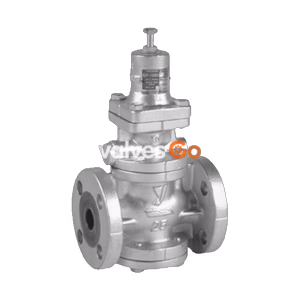
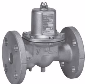
Yoshitake GD-27-NE direct type pressure reducing valve for cold and hot water. Features a closed structure, low noise design, and NPb-treated cast bronze construction for sizes 25A-100A.
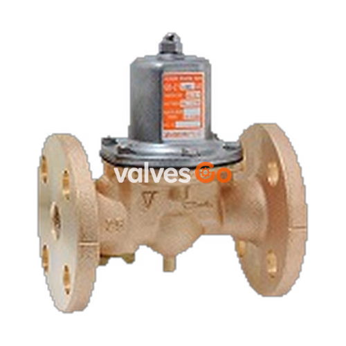
The Yoshitake GD-27-NE is a direct-type pressure reducing valve designed for cold and hot water applications. It maintains a constant reduced pressure regardless of inlet pressure fluctuations, thanks to its balanced pressure structure. Featuring a closed design to keep fluid contained even if the diaphragm is damaged, and constructed with NPb-treated cast bronze wetted parts, the GD-27-NE ensures safe, rust-free operation.
| Specification | Value |
|---|---|
| Application | Cold and hot water |
| Inlet pressure | 1.0 MPa or less |
| Reduced pressure | (A) 0.05-0.35 MPa (B) 0.30-0.70 MPa |
| Minimum differential pressure | 0.05 MPa |
| Maximum pressure reduction ratio | 10:1 |
| Application temperature | 5~90℃ |
| Body / Valve seat | Cast Bronze (NPb-treated) |
| Valve disc | FKM |
| Diaphragm | EPDM |
| Connection | JIS 10K FF flanged |
INFO
A strainer (40 mesh) is incorporated in sizes 25A to 50A. Sizes 65A to 100A do not include a strainer. Pressure gauge connection port is JIS R1/8 (maximum temperature 45℃; use a siphon tube if higher). Conformant to the Japanese Water Supply Act.
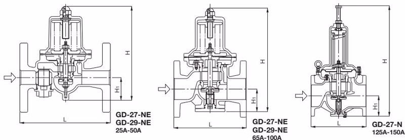
| Nominal size | L (mm) | H (mm) | H1 (mm) | Weight (kg) |
|---|---|---|---|---|
| 25A | 160 | 170 | 41 | 5.1 |
| 32A | 200 | 224 | 57 | 7.5 |
| 40A | 200 | 224 | 57 | 7.7 |
| 50A | 220 | 239.5 | 61 | 10.9 |
| 65A | 220 | 329 | 77 | 20.0 |
| 80A | 230 | 345 | 82 | 22.0 |
| 100A | 270 | 412 | 94 | 33.0 |
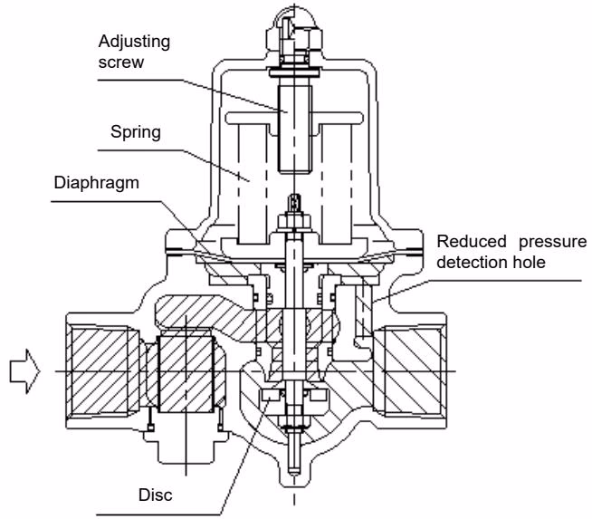
The spring is compressed by the adjusting screw, pushing the diaphragm down, and thereby opening the disc directly connected to it. Fluid from the inlet side flows out from the upper part of the disc to the outlet side, passes through the reduced pressure detection hole, and is led to the bottom of the diaphragm. The load of the spring and the reduced pressure act on the diaphragm, maintaining balance and regulating the valve opening to keep the reduced pressure constant.
| Nominal size | 25A | 32A | 40A | 50A | 65A | 80A | 100A |
|---|---|---|---|---|---|---|---|
| Rated flow (L/min) | 60 | 100 | 150 | 250 | 300 | 450 | 700 |
Nominal size 25A to 50A: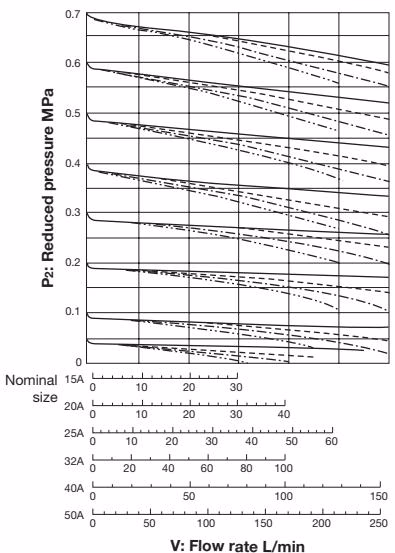
Nominal size 65A to 100A: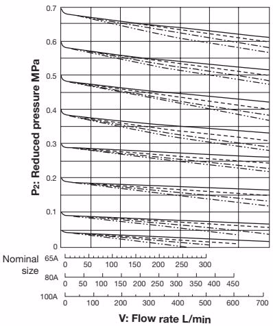
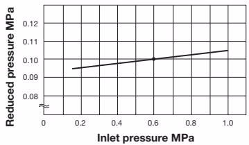 Shows variation in reduced pressure when the inlet pressure of 0.6 MPa is changed between 0.15 MPa and 1.0 MPa while the reduced pressure is set at 0.1 MPa.
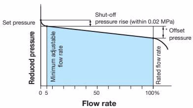
Offset pressure:
| Nominal size | Pressure range | Reduced pressure range | Offset pressure |
|---|---|---|---|
| 25-100A | A | 0.05-0.35 MPa | Within 0.05 MPa |
| 25-100A | B | 0.30-0.70 MPa | Within 0.10 MPa |
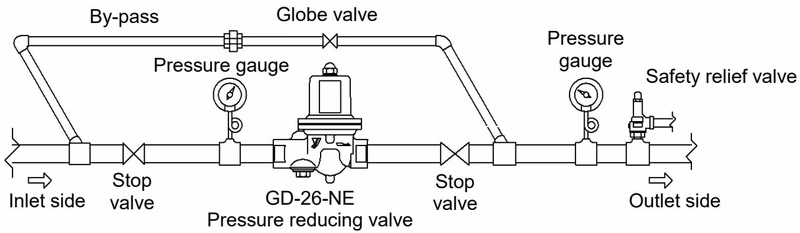
Precaution for Installation
| Trouble | Cause | Remedy |
|---|---|---|
| Abnormal pressure rises at outlet | Foreign substances on disc/seat, damaged O-ring or diaphragm, or bypass valve leakage. | Disassemble and clean/replace damaged parts or repair bypass valve. |
| Reduced pressure does not reach value | Improper working pressure, undersized valve, clogged strainer, or improper adjustment. | Correct pressure/sizing, readjust, or clean strainer. |
| Outside leakage | Loosened bolts/cap or damaged O-ring. | Tighten bolts/cap or replace O-ring. |
| Abnormal sound | Oversized valve, excessive pressure drop, air binding, or quick-operating valve nearby. | Resize valve, reduce pressure in two stages, install air vent, or relocate quick-operating valve. |
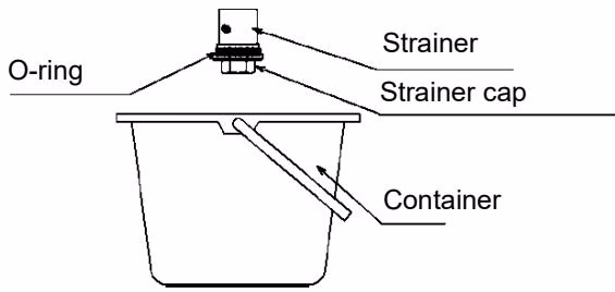 Clean the built-in strainer at least once or twice a year.
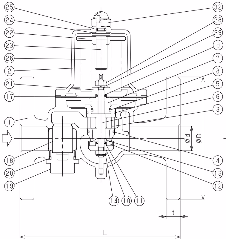
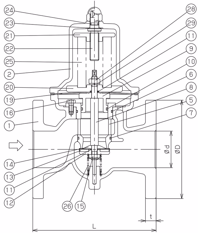
Main Parts (25A-100A):
| No. | Name of Parts | Material |
|---|---|---|
| 1 | Body | Bronze (CAC406) |
| 2 | Spring Chamber | Aluminium / Cast Iron |
| 3 | Valve Seat | Bronze (CAC406) |
| 6 | Spindle | Stainless Steel |
| 8/13 | Disc | FKM |
| 17/19 | Diaphragm | EPDM |
| 23/22 | Adjusting Screw | Stainless Steel |
| 26/25 | Spring | Alloy Steel |
Explore similar products in our catalog