Lift Type
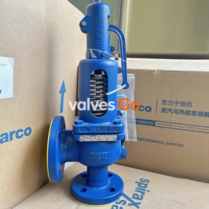
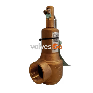
Yoshitake AL-260 and AL-260R cast bronze relief valves are closed-type safety valves with stainless steel trims. Suitable for water, oil, and non-dangerous fluids up to 1.0 MPa.
Yoshitake AL-260 and AL-260R relief valves are designed to regulate pulsating and fluctuating pressures, commonly serving large-capacity pump applications. The AL-260 features a closed-type structure, while the AL-260R includes a manual handle for easy pressure adjustments. Constructed with a cast bronze spring case and stainless steel trim parts, these valves provide stable operation against back pressure changes during continuous blow and effectively prevent chattering and hunting.
Related Models
The operational and maintenance procedures in the source documentation also apply to the AL-250 and AL-250R series, which share the same fundamental design but feature a cast stainless steel spring case.
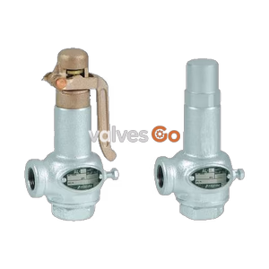
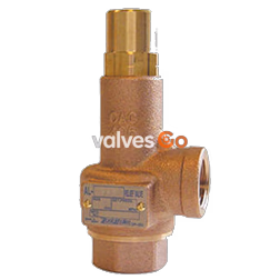
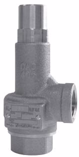 AL-260
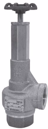 AL-260R
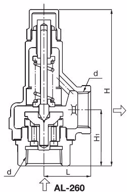
| Nominal size | d | L | H1 | H | Weight (kg) |
|---|---|---|---|---|---|
| 15A | Rc 1/2 | 34 | 41.0 | 129 (185) | 0.7 (1.0) |
| 20A | Rc 3/4 | 38 | 45.0 | 131 (190) | 0.9 (1.2) |
| 25A | Rc 1 | 43 | 51.5 | 145 (200) | 1.2 (1.5) |
| 32A | Rc 1-1/4 | 50 | 63.5 | 184 (245) | 1.9 (2.2) |
| 40A | Rc 1-1/2 | 60 | 68.5 | 210 (280) | 2.8 (3.2) |
| 50A | Rc 2 | 75 | 80.0 | 250 (315) | 4.9 (5.3) |
Note: The values in parentheses are the dimensions and weights of the AL-260R.
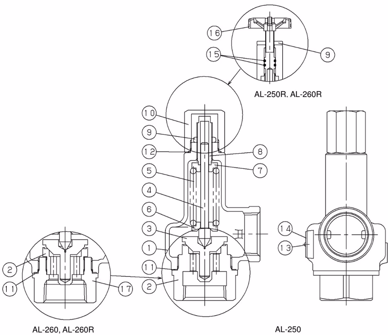
| No. | Part name | No. | Part name | No. | Part name |
|---|---|---|---|---|---|
| 1 | Spring case | 7 | Top spring plate | 13 | Rivet |
| 2 | Valve seat | 8 | Adjusting screw | 14 | Name plate |
| 3 | Valve | 9 | Lock nut | 15 | O ring |
| 4 | Spindle | 10 | Cap | 16 | Handle |
| 5 | Spring | 11 | Gasket | 17 | Valve Case |
| 6 | Bottom spring plate | 12 | Gasket |
When the pressure on the inlet side of the relief valve increases and approaches the blowout pressure, the force of the liquid pressure pushes the valve upward against the force of the spring. The valve opens further as pressure increases, releasing the fluid. The pressure is controlled by changing the degree of the valve opening depending on the inlet pressure.
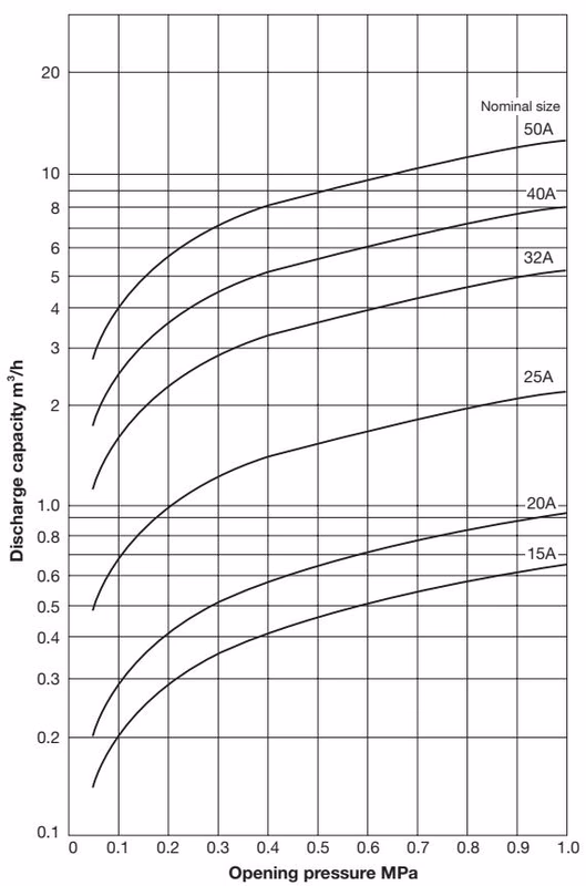
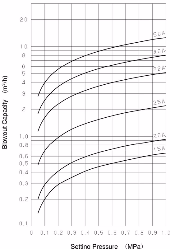
| Nominal size | 0.05 MPa | 0.1 MPa | 0.2 MPa | 0.3 MPa | 0.4 MPa | 0.5 MPa | 0.6 MPa | 0.7 MPa | 0.8 MPa | 0.9 MPa | 1.0 MPa |
|---|---|---|---|---|---|---|---|---|---|---|---|
| 15A | 0.14 | 0.20 | 0.29 | 0.35 | 0.41 | 0.46 | 0.50 | 0.54 | 0.58 | 0.62 | 0.65 |
| 20A | 0.20 | 0.29 | 0.41 | 0.51 | 0.59 | 0.66 | 0.72 | 0.78 | 0.83 | 0.88 | 0.93 |
| 25A | 0.49 | 0.69 | 0.98 | 1.20 | 1.38 | 1.54 | 1.69 | 1.83 | 1.96 | 2.07 | 2.19 |
| 32A | 1.14 | 1.62 | 2.29 | 2.81 | 3.24 | 3.63 | 3.97 | 4.29 | 4.59 | 4.87 | 5.13 |
| 40A | 1.79 | 2.53 | 3.58 | 4.39 | 5.07 | 5.67 | 6.21 | 6.71 | 7.17 | 7.61 | 8.02 |
| 50A | 2.80 | 3.96 | 5.60 | 6.86 | 7.92 | 8.86 | 9.71 | 10.49 | 11.21 | 11.89 | 12.53 |
(Values represent flow rate for water in m³/h)
If the accumulation is not 25%, use the approximate flow rate magnification chart below to select the corresponding multiplier, and multiply it by the flow rate value at 25% accumulation.
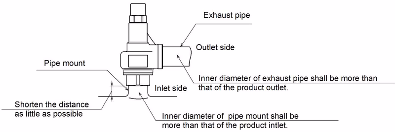
General Piping Cautions
WARNING
To adjust the set pressure, turn the adjusting screw (or the handle in the case of AL-260R) slowly at a rotation of 1/4-1/3 and confirm the operation each time. Be careful of sudden blowout if the handle is turned too much.
Do not adjust the setting pressure beyond the bounds of its classification.
| Nominal size | A | B | C | D | E | F |
|---|---|---|---|---|---|---|
| 15A | 0.05~0.2 | 0.21~0.4 | 0.41~0.55 | 0.56~0.75 | 0.76~1.0 | — |
| 20A | 0.05~0.2 | 0.21~0.35 | 0.36~0.45 | 0.46~0.6 | 0.61~0.75 | 0.76~1.0 |
| 25A | 0.05~0.2 | 0.21~0.35 | 0.36~0.45 | 0.46~0.55 | 0.56~0.8 | 0.81~1.0 |
| 32A | 0.05~0.2 | 0.21~0.4 | 0.41~0.65 | 0.66~1.0 | — | — |
| 40A | 0.05~0.2 | 0.21~0.4 | 0.41~0.65 | 0.66~0.8 | 0.81~1.0 | — |
| 50A | 0.05~0.2 | 0.21~0.4 | 0.41~0.65 | 0.66~0.8 | 0.81~1.0 | — |
| Trouble | Cause | Remedy |
|---|---|---|
| Blows at a pressure lower than the set pressure. | 1. Specifications are not consistent with the use condition. 2. Pressure gauge is out of order. 3. Foreign substance or scale stuck on contact surface. 4. Damage on contact surface of valve and valve seat. 5. Product does not keep the accuracy of its set pressure. | 1. Check set pressure indication on name plate. Replace if unsuitable. 2. Calibrate or replace gauge. 3. Operate product and eliminate substance. 4. Disassemble and replace parts. 5. Readjust set pressure. |
| Does not operate at the set pressure. | 1. Specifications are not consistent with the use condition. 2. Product does not keep the accuracy of its set pressure. 3. Pressure gauge is out of order. 4. Sliding parts do not move smoothly. 5. Back pressure at the piping of the product outlet. | 1. Check set pressure indication. Replace if unsuitable. 2. Readjust set pressure. 3. Calibrate or replace gauge. 4. Disassemble and clean. 5. Change piping layout to eliminate back pressure. |
| Does not stop blowing. | 1. Foreign substance or scale stuck on contact surface. 2. Damage on contact surface of valve and valve seat. 3. Sliding parts do not move smoothly. 4. Normal working pressure exceeds the closing pressure. 5. Product installed at outlet of a malfunctioning PRV. | 1. Disassemble and clean. 2. Disassemble and replace parts. 3. Disassemble and clean. 4. Increase difference between set pressure and working pressure. 5. Repair the pressure reducing valve. |
| Leakage from between cap and O-ring (AL-250R/AL-260R) | Damage on the O ring. | Disassemble and replace the O ring. |