Up to 99.8% Efficiency

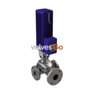
TLV MC-COSR-3 and MC-COSR-16 high-precision motorized multi-control valves for steam. Features a rapid response brushless motor for accurate pressure and temperature control.
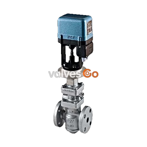
TLV MC-COSR-3 and MC-COSR-16 high-precision multi-control valves for steam provide accurate pressure control and temperature control when combined with the TLV SC-F70 or SC-F71 digital indicator controller. The valve consists of the COSR pressure reducing valve and a motorized actuator (MC-GA2). The rapid response brushless motor precisely adjusts the valve position to ensure extremely accurate control, even during adverse process conditions.
WARNING
Install properly and DO NOT use this product outside the recommended operating pressure, temperature and other specification ranges. Improper use may result in such hazards as damage to the product or malfunctions which may lead to serious accidents.
INFO
MC-COSR-3 cannot be used for temperature control applications.
| Model | MC-COSR-3 | MC-COSR-16 |
|---|---|---|
| Connection | Flanged | Flanged |
| Size (DN) | 20, 25, 32, 40, 50 | 15, 20, 25, 32, 40, 50, 65, 80, 100, 150 |
| Body Material | Ductile Cast Iron / Cast Iron | Ductile Cast Iron / Cast Iron |
| Max. Operating Pressure (barg) | 3 | 16 (Ductile Cast Iron) / 13 (Cast Iron) |
| Max. Operating Temperature (°C) | 220 | 220 (Ductile Cast Iron) / 200 (Cast Iron) |
| Primary Pressure Range (barg) | 1 - 3 | 2 - 16 (Ductile Cast Iron) / 2 - 13 (Cast Iron) |
| Adjustable Pressure Range | 0.1 - 0.5 barg | Within 10 - 84% of primary pressure (min. 0.3 barg) |
| Minimum Adjustable Flow Rate | 5% of rated flow rate | 5% of rated flow rate (DN 65 - 150: 10%) |
| Parameter | Specification |
|---|---|
| Actuator Model | MC-GA2 |
| Power Source Voltage | Free between 100 and 240 V AC (50/60 Hz) |
| Power Consumption | With motor running: 75 VA max. |
| Drive System | Positional control by DC brushless motor |
| Operation Input | 4 – 20 mA DC (input impedance: approx. 250 Ω) |
| Emergency Action | Valve fully closed by an operation signal interruption. When input power is cutoff: held at position just before power was cut off |
| Time Required to Fully Open/Close | Fully closed ↔ fully open: Approx. 15 seconds |
| Allowable Ambient Temperature | 0 to 50 °C (32 to 122 °F) |
| Water Resistance | Rain resistant (equivalent to IP54) |
| Size (DN) | 15* | 20 | 25 | 32 | 40 | 50 | 65* | 80* | 100* | 150* |
|---|---|---|---|---|---|---|---|---|---|---|
| Kvs (DIN) | 3.3 | 5.9 | 9.5 | 13.3 | 20.6 | 31.9 | 50.8 | 72.9 | 110 | 236 |
| Cv (UK) | 3.2 | 5.7 | 9.2 | 12.9 | 20.0 | 31.0 | 49.4 | 70.8 | 107 | 229 |
| Cv (US) | 3.8 | 6.9 | 11.1 | 15.5 | 24.0 | 37.2 | 59.3 | 85.0 | 128 | 275 |
MC-COSR-16 only. The Cv & Kvs values shown are for the valve in the full fail open position. These values are not to be used for MC-COSR sizing, and instead may be used as one of the factors in calculations for safety valve selection.
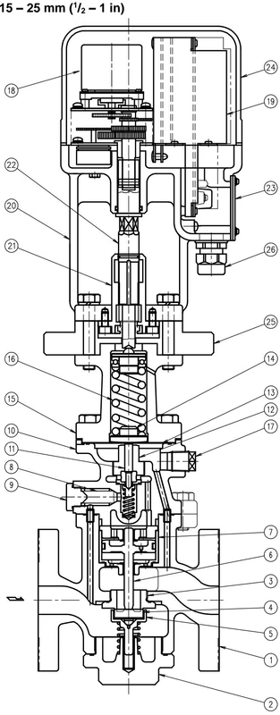
| No. | Name | No. | Name |
|---|---|---|---|
| 1 | Main Body | 14 | Diaphragm Support |
| 2 | (Main Body) Plug / Cover | 15 | Spring Housing |
| 3 | Main Valve Seat | 16 | Coil Spring |
| 4 | Main Valve | 17 | Plug – Sensing Line Port |
| 5 | Main Valve Holder | 18 | Motor Unit |
| 6 | Piston | 19 | Drive Unit |
| 7 | Cylinder | 20 | Mounting Plate |
| 8 | Pilot Screen | 21 | Adjustment Screw Guide |
| 9 | Pilot Screen Holder | 22 | Adjustment Screw |
| 10 | Pilot Body | 23 | Terminal Block Cover |
| 11 | Pilot Valve Stem | 24 | Motor Cover |
| 12 | Pilot Valve Seat | 25 | Insulation Plate |
| 13 | Diaphragm | 26 | Cable Lock |
In order to ensure stable steam flow, the piping upstream and downstream of the MC-COSR must be straight runs. If a MC-COSR is installed either directly before or after an elbow or control valve, unevenness in steam flow may result in chattering and unstable pressure.
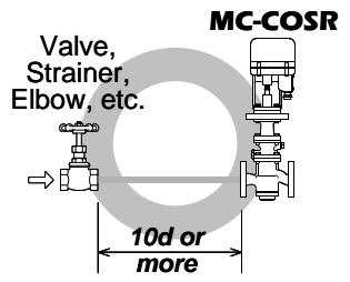
Maintain a straight piping run of 10 d or more when a manual valve, a strainer or an elbow, etc. is installed at the inlet (primary side) of the MC-COSR.
TIP
If an on-off valve, such as a motorized valve, is required to stop supply of steam to the steam-using equipment, install it at the inlet side of the MC-COSR. To prevent water hammer, it is recommended that a slow-acting motorized on-off valve be used.
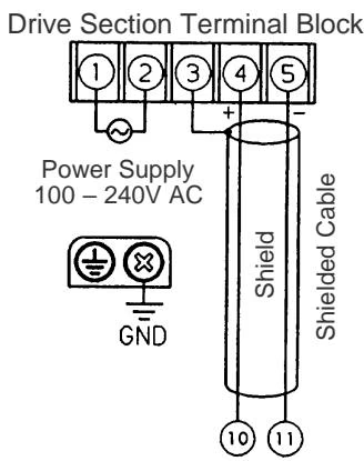
Background electromagnetic noise that has no effect on analog equipment may cause digital equipment to malfunction or fail. To prevent adverse effects from electro-magnetic (EM) interference, carefully follow the wiring instructions.
1. Power Source Install an overcurrent protection device on the power supply lines (both poles) to prevent overcurrent. Recommended rating of the device: 250V/2A, Delay type.
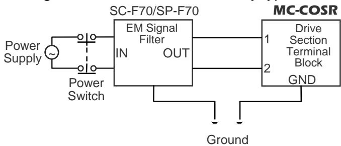
2. Terminal Block When making a connection to the terminal block, use crimp-style jacks (for M4) with insulation sleeves.
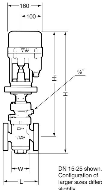
| DN | L (DIN 2501 PN25/40) | L (ASME 150RF) | L (ASME 300RF) | H | H1 | W | Weight (kg) |
|---|---|---|---|---|---|---|---|
| 15** | 130 | 170 | 170 | 582 | 510 | 88 | 17 |
| 20 | 150 | 182 | 182 | 582 | 510 | 88 | 17 |
| 25 | 160 | 188 | 192 | 507 | 510 | 93 | 19 |
| 32 | 180 | 220 | 220 | 610 | 520 | 126 | 24 |
| 40 | 200 | 222 | 224 | 610 | 520 | 126 | 25 |
| 50 | 230 | 255 | 261 | 637 | 540 | 157 | 32 |
| 65** | 290 | 372 | 378 | 778 | 635 | 220 | 59 |
| 80** | 310 | 374 | 384 | 778 | 635 | 220 | 62 |
| 100** | 350 | 434 | 450 | 857 | 672 | 265 | 86 |
| 150** | 480 | 600 | 622 | 1035 | 755 | 330 | 192 |
( ) No ASME standard exists for cast iron; machined to fit steel flanges. ** MC-COSR-16 only.
Explore similar products in our catalog