


PN16

TLV JH3-X and JH3-B stainless steel free float steam traps with thermostatic air venting. Suitable for small-size process equipment up to 32 barg.
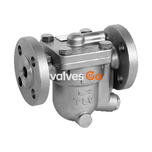
TLV JH3-X and JH3-B are reliable and durable stainless steel free float steam traps with thermostatic air venting, designed for use on small-size process equipment. The inline repairable JH-X series is suitable for a wide range of applications with small-to-large capacities and pressures up to 32 barg (3.2 MPaG), such as heat exchangers, process heaters, and coils. The JH3-B model is also suitable for both superheated and high-pressure process equipment.
The traps discharge condensate continuously and automatically, at a temperature slightly lower than saturation temperature.
| Model | JH3-X | JH3-B |
|---|---|---|
| Connection | Flanged | Flanged |
| Size | DN 15, 20, 25 | DN 15, 20, 25 |
| Orifice No. | 2, 5, 10, 14, 22, 32 | 2, 5, 10, 14, 22, 32 |
| Maximum Operating Pressure (PMO) | 2, 5, 10, 14, 22, 32 barg | 2, 5, 10, 14, 22, 32 barg |
| Maximum Differential Pressure (ΔPMX) | 2, 5, 10, 14, 22, 32 bar | 2, 5, 10, 14, 22, 32 bar |
| Maximum Operating Temperature (TMO) | 240 °C | 350 °C |
| Type of Air Vent | X-element (6 °C subcooling) | Bimetal (vents air up to approx. 100 °C) |
PRESSURE SHELL DESIGN CONDITIONS
Maximum allowable pressure (PMA) and maximum allowable temperature (TMA) are PRESSURE SHELL DESIGN CONDITIONS, NOT OPERATING CONDITIONS.
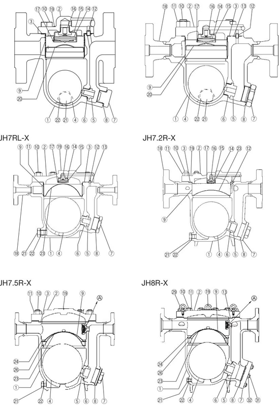
| No. | Description | No. | Description | No. | Description |
|---|---|---|---|---|---|
| 1 | Body | 12 | Connector | 23 | Screen Holder |
| 2 | Cover | 13 | Connector Gasket | 24 | Snap Ring |
| 3 | Cover Gasket | 14 | X-element | 25 | Snap Ring |
| 4 | Float | 15 | X-element Guide | 26 | Screen Holder Retainer |
| 5 | Orifice | 16 | Air Vent Valve Seat | 27 | X-element Case |
| 6 | Orifice Gasket | 17 | Spring Clip | 28 | X-element Screen |
| 7 | Orifice Plug or Outlet Cover | 18 | Flange or Socket | 29 | Eye Bolt |
| 8 | Plug or Outlet Cover Gasket | 19 | Nameplate | 30 | X-element Case Gasket |
| 9 | Screen | 20 | Float Cover | 31 | Outlet Cover Bolt |
| 10 | Cover Bolt | 21 | Drain Plug* | 32 | Outlet Cover Nut |
| 11 | Cover Nut | 22 | Drain Plug Gasket* |
* Option for JH3-X
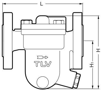
JH3-X / JH3-B Flanged (mm)
| DN | L (DIN 2501 PN25/40) | H | H1 | Weight (kg) |
|---|---|---|---|---|
| 15 | 150 | 132 | 84 | 3.4 |
| 20 | 140 | 132 | 90 | 3.6 |
| 25 | 160 | 147 | 92 | 4.6 |
JH3-X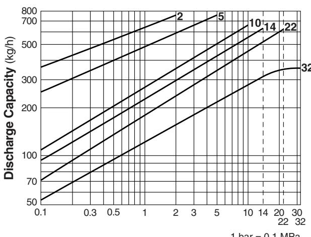
JH3-B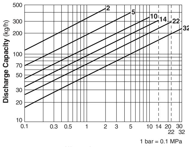
Capacity Notes
WARNING
NEVER apply direct heat to the float. The float may explode due to increased internal pressure, causing accidents leading to serious injury or property and equipment damage.
A visual inspection can be carried out to aid in determining the necessity for immediate maintenance or repair, if the trap is open to atmosphere.
| Status | Description |
|---|---|
| Normal | Condensate is discharged continuously with flash steam and the sound of flow can be heard. If there is very little condensate, there is almost no sound of flow. |
| Blocked | No condensate is discharged. The trap is quiet and makes no noise, and the surface temperature of the trap is low. |
| Blowing | Live steam continually flows from the outlet and there is a continuous metallic sound. |
| Steam Leakage | Live steam is discharged through the trap outlet together with the condensate and there is a high-pitched sound. |
If the expected performance is unachievable after installation, check the following points:
| Problem | Cause | Remedy |
|---|---|---|
| No condensate is discharged (blocked) or discharge is poor | Float is damaged or filled with condensate | Replace the float |
| Orifice, screen or piping are clogged with rust or scale | Clean | |
| X-element is damaged | Replace the X-element | |
| The trap operating pressure exceeds the maximum specified pressure, or there is insufficient pressure differential | Compare specifications and actual operating conditions | |
| Steam locking has occurred | Blowdown through the bypass or close the trap inlet valve and allow the trap to cool | |
| Steam is discharged or leaks from the trap outlet (blowing / steam leakage) | Rust and scale have accumulated around the orifice or under the float | Clean |
| Orifice is damaged | Replace with new orifice | |
| Float is deformed or coated with scale | Clean or replace the float | |
| Trap is installed above the maximum allowable inclination angle | Correct the installation | |
| Vibration of trap occurs | Lengthen inlet piping, then fasten it securely | |
| The X-element is damaged, or clogged with rust or scale | Clean or replace the X-element | |
| Steam leaks from a place other than the trap outlet | Deterioration of or damage to gaskets | Replace the gaskets |
| Leakage from eroded cavities of body or cover | Replace the trap | |
| Improper tightening torque for cover was used | Tighten to the proper torque | |
| Float is frequently damaged | Water hammer occurs | Examine the piping for problems that can cause water hammer |




