


PN16

TLV J10 series cast iron float-piston steam trap for high-capacity process applications. Features a self-modulating free float pilot, 13 barg max pressure, and 220°C max temperature.
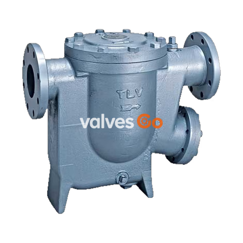
The TLV J10 series is an inline maintainable, float dynamic steam trap capable of discharging condensate at high flow rates. It is specifically designed as a cast iron float-piston trap for high-capacity process applications, making it highly suitable for large process heat exchangers.
This product features a self-modulating free float pilot mechanism that ensures discharge at near-to-steam temperatures, combined with a proven piston valve that allows "pulsing" discharge of condensate at high flow rates and intermittent discharge at low flow rates.
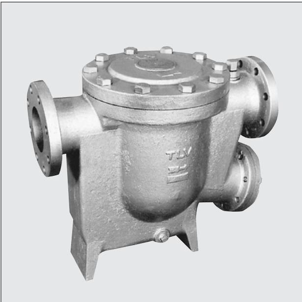
| Model | J10-30 | J10-60 |
|---|---|---|
| Connection | Flanged | Flanged |
| Size (mm) | 100 | 100 |
| Maximum Operating Pressure (barg) PMO | 13 | 13 |
| Maximum Differential Pressure (bar) ΔPMX | 13 | 13 |
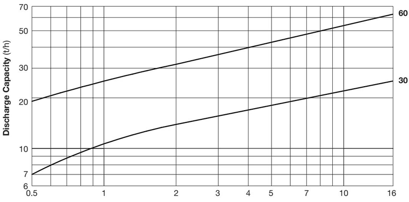
| Minimum Differential Pressure (bar) | 0.5 | 0.5 |
| Maximum Operating Temperature (°C) TMO | 220 | 220 |
Pressure Shell Design Conditions
Maximum Allowable Pressure (barg) PMA: 13 (1 MPa = 10.197 kg/cm²) Maximum Allowable Temperature (°C) TMA: 220 These are NOT operating conditions. Install properly and DO NOT use this product outside the recommended operating pressure, temperature and other specification ranges.
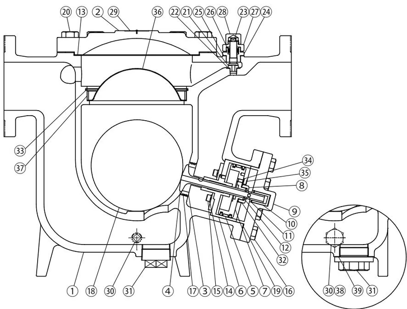
| No. | Description | Material | DIN* | ASTM/AISI* |
|---|---|---|---|---|
| 1 | Body | Cast Iron FC250 | GG-25 | A126 CI.B |
| 2 | Cover | Cast Iron FC250 | GG-25 | A126 CI.B |
| 3 | Float | Stainless Steel SUS316L | 1.4404 | AISI316L |
| 4 | Sleeve | Stainless Steel SUS420F | 1.4028 | AISI420F |
| 5 | Float Cover | Stainless Steel SUS304 | 1.4301 | AISI304 |
| 15 | Main Valve | - | - | - |
| 16 | Main Valve Seat | - | - | - |
| 17 | Cylinder | Stainless Steel SUS304 | 1.4301 | AISI304 |
| 18 | Piston Ring Set | Stainl. Stl./Fluorine Resin SUS304/PTFE | 1.4301/PTFE | AISI304/PTFE |
| 19 | Piston | Stainless Steel SUS304 | 1.4301 | AISI304 |
| 23 | Lock Release Valve | Stainless Steel SUS420F | 1.4028 | AISI420F |
(Note: Partial list of key components. Refer to the full manual for all 24 parts.)
Float Warning
NEVER apply direct heat to the float. The float may explode due to increased internal pressure, causing accidents leading to serious injury or damage to property and equipment.
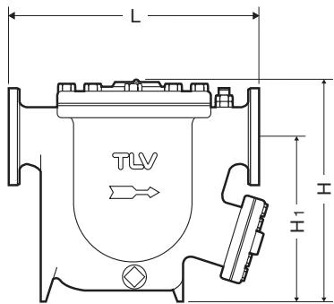
J10 Flanged (mm)
| Size | L (DIN PN16) | L (ASME 125FF) | L (ASME 150RF) | L (ASME 250RF) | L (ASME 300RF) | H | H1 | Weight* (kg) |
|---|---|---|---|---|---|---|---|---|
| 100 | 595 | 595 | 595 | 611 | 611 | 510 | 395 | 121 |
No ASME standard exists for cast iron; machined to fit steel flanges. Class 125 FF can connect to 150 RF, 250 RF can connect to 300 RF. Weight is for Class 250 RF.
WARNING
DO NOT use traps under conditions that exceed maximum differential pressure, as condensate backup will occur!
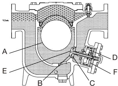
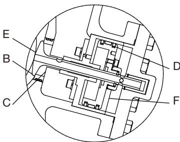
At start-up, when a large quantity of condensate flows into the trap, the float (A) rises by buoyancy, opening the pilot orifice (E). Condensate flows through the pilot orifice (E) into the control chamber (F), increasing the pressure there. The increased pressure causes the piston (D), and accordingly the main valve (B), to move up. The orifice on the main valve seat (C) is then opened to discharge condensate.
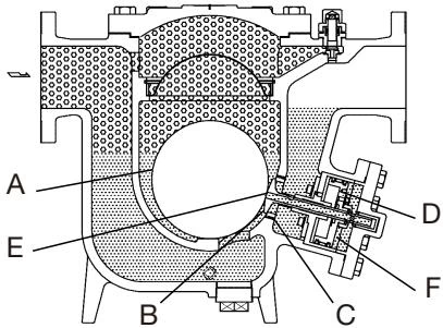
When condensate has been discharged, the float (A) falls, closing the pilot orifice (E). Pressure in the control chamber (F) decreases due to leakage through small holes. The main valve (B) moves downward, closing the orifice of the main valve seat (C). The orifices are completely water-sealed during operation, permitting no steam leakage.
After the large quantity of initial condensate formed at start-up has been discharged, the equipment reaches a thermally balanced state, forming condensate in accordance with the load. The trap then discharges condensate by a modulating float dynamic principle.
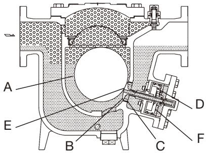
When a large quantity of condensate flows into the trap, the float (A) rises immediately, opening the pilot orifice (E) wide. Condensate passes through the pilot orifice at a high velocity into the control chamber (F), where the pressure increases rapidly due to flashing condensate. The rapid expansion causes a force to be exerted on the main valve (B), opening the large orifice on the main valve seat (C) instantly. As condensate discharges through the main valve seat orifice at a high velocity, condensate in the equipment and trap inlet pipe is also discharged.
If air binding or steam-locking occurs, or to more rapidly vent large quantities of initial air in the piping, use the lock release valve.
WARNING
Do not leave the lock release valve open during regular operation. Always be sure to close the lock release valve after eliminating air binding or steam-locking.
If the product fails to operate properly, use the following table to locate the cause and remedy.
| Problem | Cause | Remedy |
|---|---|---|
| No condensate is discharged (blocked) or discharge is poor | The float is damaged or filled with condensate | Replace with a new float |
| There is no inflow of condensate | Inspect and correct the piping | |
| The orifice opening or piping are clogged with rust and scale | Clean parts | |
| The product operating pressure exceeds the maximum specified pressure or there is insufficient pressure differential | Compare specifications and actual operating conditions | |
| Air binding or steam-locking has occurred | Operate the lock release valve, perform a bypass blowdown or close the product inlet valve and allow the product to cool | |
| The piston or cylinder is damaged or the exhaust holes in the main valve stem have become enlarged | Replace with a new piston, cylinder or main valve | |
| Steam is discharged or leaks from the product outlet | The piston or cylinder has a build-up of sticky scale | Clean parts |
| Build-up on the seating surface of the main valve or rust and scale build-up beneath the float | Clean parts | |
| The float is misshapen or has a build-up | Clean or replace with new float | |
| The exhaust holes in the main valve have become clogged | Clean or replace piston | |
| The main valve or main valve seat is worn | Replace with new parts as required | |
| Steam is leaking from a place other than the outlet | Improper installation orientation | Correct the installation |
| Product vibration | Lengthen inlet piping and fasten securely | |
| Gasket deterioration or damage | Replace with new gasket(s) | |
| Improper tightening torques were used | Tighten to the proper torque | |
| Float is frequently damaged | Water hammer has occurred | Study and correct the piping |




