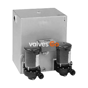
3450 RPM Motors

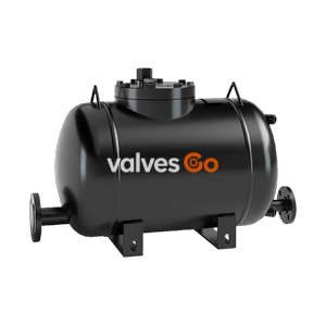
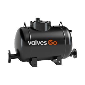
TLV GT14M PowerTrap compact mechanical pump with built-in steam trap. Handles high-temperature condensate without cavitation. Max 14 barg, 220°C.
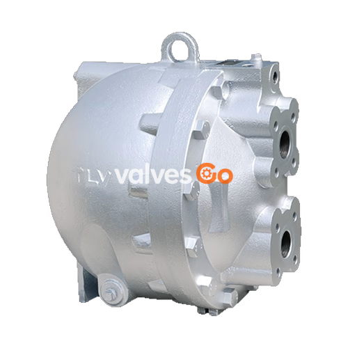
TLV GT14M PowerTrap is a compact mechanical pump with a built-in steam trap designed for condensate removal and recovery. It is highly suitable for the drainage of medium capacity heat exchangers, flash steam recovery systems, and reservoirs, often operating under vacuum conditions. The GT model features a built-in trap function, making it suitable for use in instances where the inlet pressure may alternately be lower than or higher than the outlet pressure.
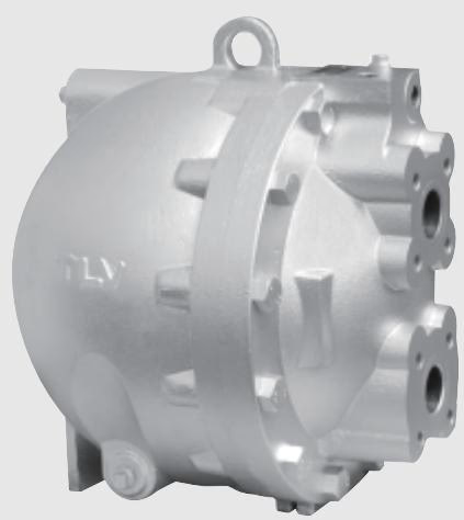
| Specification | Value |
|---|---|
| Body Material | Cast Iron (FC250) / Cast Steel (A216 Gr.WCB) |
| Pumped Medium Inlet & Outlet | DN 40 × DN 40 (Flanged) |
| Motive Medium & Pump Exhaust | 1/2" (Screwed) |
| Maximum Operating Pressure (PMO) | 13 barg (Cast Iron) / 14 barg (Cast Steel) |
| Maximum Operating Temperature (TMO) | 200 °C (Cast Iron) / 220 °C (Cast Steel) |
| Motive Medium Pressure Range | 0.3 – 13 barg (Cast Iron) / 0.3 – 14 barg (Cast Steel) |
| Maximum Allowable Back Pressure | 0.5 bar less than motive medium pressure used |
| Volume of Each Discharge Cycle | Approx. 12.5 liters |
| Motive Medium | Saturated Steam |
| Pumped Medium | Steam Condensate, Water |
WARNING
Install properly and DO NOT use this product outside the recommended operating pressure, temperature and other specification ranges. Improper use may result in such hazards as damage to the product or malfunctions which may lead to serious accidents.
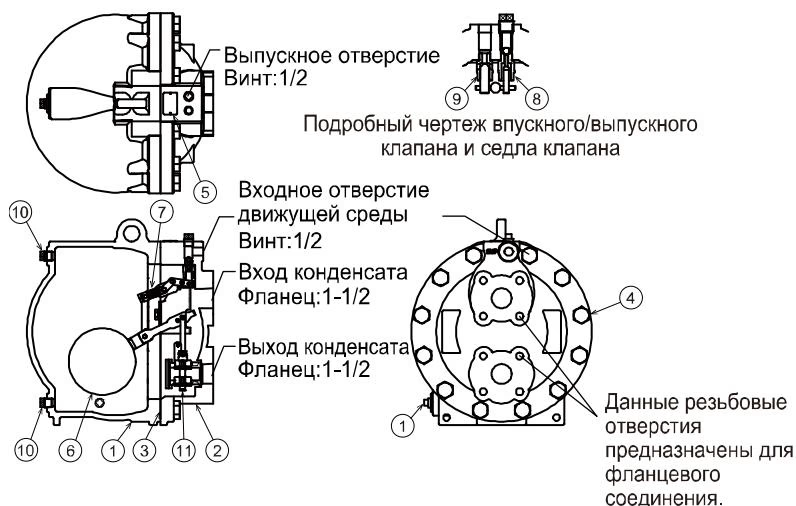
| No. | Description | Material | DIN | ASTM/AISI |
|---|---|---|---|---|
| 1 | Body | Cast Iron FC250 / Cast Steel | 0.6025 / 1.0619 | A126 Cl.B / A216 Gr.WCB |
| 2 | Cover | Cast Iron FC250 / Cast Steel | 0.6025 / 1.0619 | A126 Cl.B / A216 Gr.WCB |
| 3 | Cover Gasket | Graphite Compound | — | — |
| 4 | Float | Stainless Steel SUS316L | 1.4404 | AISI316L |
| 5 | Snap-action Unit | Stainless Steel | — | — |
| 6 | Motive Medium Intake Valve Unit | Stainless Steel SUS440C / SUS420F | 1.4125 / 1.4028 | AISI440C / AISI420F |
| 7 | Exhaust Valve Unit | Stainless Steel SUS440C / SUS420F | 1.4125 / 1.4028 | AISI440C / AISI420F |
| 8 | Steam Trap Unit | Stainless Steel | — | — |
| 9 | Inlet Check Valve CKF5M | Stainless Steel SUS304 | 1.4301 | AISI304 |
| 10 | Outlet Check Valve CKF3M | Cast Stainless Steel A351 Gr.CF8 | 1.4312 | — |
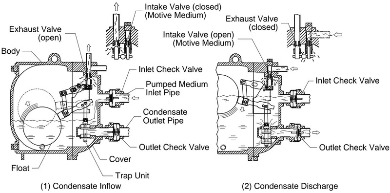
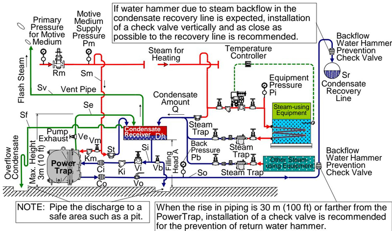
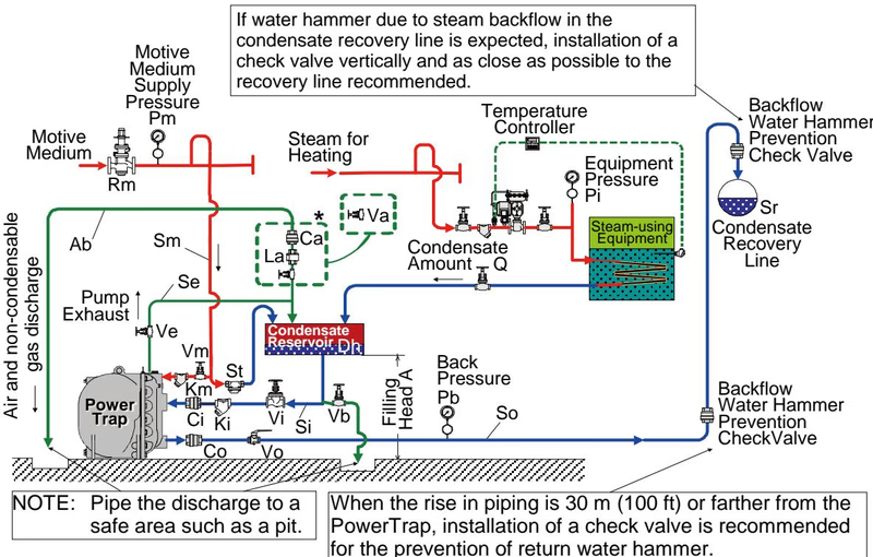
The PowerTrap is used to discharge liquid from vacuum-pressure or low-pressure areas to high-pressure areas, or from lower to higher elevations. There are two types of delivery systems: the closed system and the open system.
TIP
Only TLV check valves supplied with PowerTrap should be used; proper discharge capacity cannot be guaranteed with other check valves. The CKF5M is a swing type check valve for the condensate inlet and must be installed with the "UP" mark pointing upwards. The CKF3M is a disc check valve for the condensate outlet and can be installed in any orientation.
The reservoir must have a capacity sufficient to store the condensate produced during the PowerTrap operation and discharge. When flash steam is not involved, refer to the following table to determine the reservoir pipe diameter and length based on the amount of condensate:
| Amount of Condensate (kg/h) | Reservoir Diameter 100 mm | Reservoir Diameter 150 mm | Reservoir Diameter 200 mm | Reservoir Diameter 250 mm |
|---|---|---|---|---|
| 1000 | 0.7 m | - | - | - |
| 2000 | 1.3 m | 0.6 m | - | - |
| 4000 | - | 1.2 m | 0.7 m | - |
| 6000 | - | 1.7 m | 1.0 m | 0.6 m |
| 8000 | - | - | 1.3 m | 0.8 m |
| 10000 | - | - | 1.7 m | 1.0 m |
Note: Reservoir length can be reduced by 50% when the motive medium pressure divided by back pressure equals 2 or greater.
DANGER
NEVER apply direct heat to the float. The float may explode due to increased internal pressure, causing accidents leading to serious injury or damage to property and equipment.
When disassembling or removing the product, wait until the internal pressure equals atmospheric pressure and the surface of the product has cooled to room temperature. Disassembling or removing the product when it is hot or under pressure may lead to discharge of fluids, causing burns, other injuries or damage.
Periodic inspection should be performed at least once every 2 years. Check that the snap-action moves up and down smoothly, the float is not damaged, and there is no foreign matter sticking to the shafts and levers. Always replace the body and cover gaskets with new gaskets when reassembling.
Explore similar products in our catalog