3450 RPM Motors

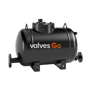
Armstrong EDD-6 (Double Duty 6) steam trap and pump combination. Low-profile carbon steel vessel, non-electric operation, and Inconel X-750 springs for draining heat exchangers.
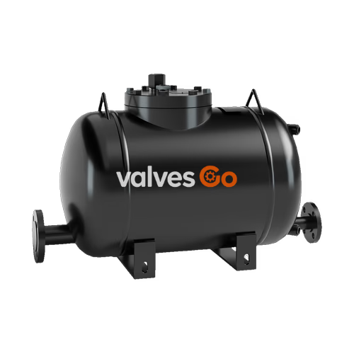
Armstrong EDD-6 (Double Duty® 6) steam trap/pump combination offers a low profile solution to draining heat exchangers in various applications. The Double Duty® 6 is a CE marked carbon steel vessel according to PED 97/23 EC (or ASME code stamped for DD-6). It offers the versatility of combining a pump within a steam trap to aid in condensate drainage under all operating conditions.
Application
When there is modulating control on heat exchange equipment, there is a possibility that the system will stall (no longer be able to drain condensate). If only a steam trap is used, condensate could flood the heat exchange equipment causing corrosion, water hammer, and poor temperature control. The Double Duty™ has a steam trap with an integral pump to prevent the system from stalling. If the condensate floods the body of the Double Duty™ and reaches its upper trip point, high pressure steam will enter the body and push the condensate out. This prevents condensate from accumulating in the heat exchange equipment.
As the condensate flows through the inlet check valve, the trap and pump floats become buoyant and rise with the fluid level. The upward movement of the float causes the trap valve to open. If the system pressure is greater than the back pressure, the condensate will flow through the steam trap valve into the condensate return.
If the system pressure is less than the back pressure, liquid floods the body. When the condensate reaches the upper trip point of the pump mechanism, the motive inlet valve opens and the vent valve closes. The open motive valve allows the motive fluid to enter and pressurize the body. The pressure inside the body shuts the inlet check valve and when it is greater than the back pressure, pushes the water through the discharge check valve into the condensate return line. The float lowers with the water level and when it reaches the lower pump trip point, the motive inlet valve closes and the vent valve opens. This relieves the pressure in the body and allows it to fill again.
| Component | Material |
|---|---|
| Body | Carbon Steel (ASME Code Stamped or CE Marked) |
| Springs | Inconel X-750 |
| Internals | All stainless steel |
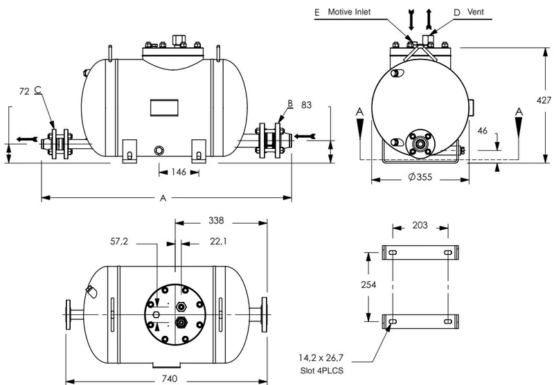
| Dimension | EDD-6 (DIN) | EDD-6 (ANSI) |
|---|---|---|
| "A" | 887 mm | 920 mm |
| "B" | DN40 | 1-1/2" |
| "C" | DN25 | 1" |
| "D" | 1" BSPT | 1" NPT |
| "E" | 1/2" BSPT | 1/2" NPT |
(Note: All dimensions and weights are approximate. Use certified print for exact dimensions.)
| Motive (bar) | Back Pressure (bar) | Capacity (kg/hr) |
|---|---|---|
| 1 | 0.34 | 1 089 |
| 1.7 | 0.34 | 1 361 |
| 3.5 | 0.34 | 1 814 |
| 5 | 0.34 | 2 041 |
| 7 | 0.34 | 2 087 |
| 8.5 | 0.34 | 2 132 |
| 10.34 | 0.34 | 2 177 |
| 12 | 0.34 | 2 177 |
| 14 | 0.34 | 2 087 |
| 1.7 | 1 | 907 |
| 3.5 | 1 | 1 270 |
| 5 | 1 | 1 542 |
| 7 | 1 | 1 633 |
| 8.5 | 1 | 1 678 |
| 10.34 | 1 | 1 724 |
| 12 | 1 | 1 633 |
| 14 | 1 | 1 588 |
| 2.5 | 1.7 | 816 |
| 3.5 | 1.7 | 1 043 |
| 5 | 1.7 | 1 315 |
| 7 | 1.7 | 1 361 |
| 8.5 | 1.7 | 1 361 |
| 10.34 | 1.7 | 1 315 |
| 12 | 1.7 | 1 134 |
| 14 | 1.7 | 1 043 |
| 3.5 | 3 | 635 |
| 5 | 3 | 907 |
| 7 | 3 | 1 089 |
| 8.5 | 3 | 1 134 |
| 10.34 | 3 | 1 134 |
| 12 | 3 | 816 |
| 14 | 3 | 771 |
| 5 | 4 | 680 |
| 7 | 4 | 816 |
| 8.5 | 4 | 907 |
| 10.34 | 4 | 771 |
| 12 | 4 | 680 |
| 14 | 4 | 635 |
Note: Published capacities are based on the use of external check valves supplied by Armstrong. Fill head measured from drain point to top of pump case.
| Differential Pressure (bar) | Capacity (kg/hr) |
|---|---|
| 0.14 | 4 309 |
| 0.34 | 5 625 |
| 0.7 | 6 804 |
| 1.7 | 9 253 |
| 3.5 | 10 206 |
| 5.2 | 10 206 |
| 6.9 | 10 206 |
| 10.3 | 10 206 |
| 13.8 | 10 206 |
| Filling Head (mm) | 0 | 150 | 300 | 600 or greater |
|---|---|---|---|---|
| Double Duty EDD-6 | 0.7 | 1.0 | 1.08 | Consult factory |
Discharge per cycle typically 13.6 litres (3.5 gallons) for EDD-6. Note: Fill head measured from drain to top of cap.
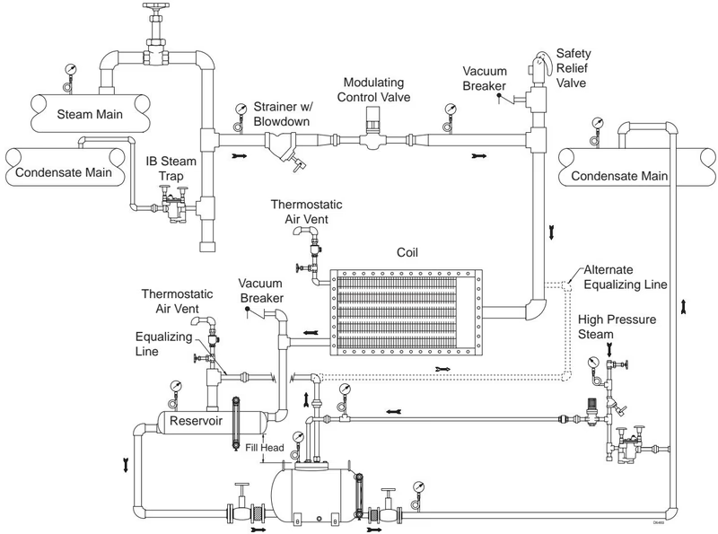
Installation Instructions
Caution
Make sure all connections are secure before opening valves. Open valves slowly to reduce the chance of water hammer.
Most failures occur because of debris in the piping.
Caution
Before starting any maintenance make sure the Double Duty™ 6 is completely isolated from the system. Make sure the system is at atmospheric pressure.
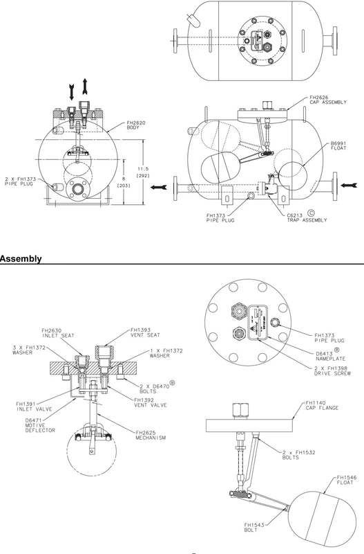
| Problem | Diagnosis | Solution |
|---|---|---|
| Condensate not discharging | Inlet isolation valve closed | Open valve |
| Pump inlet and outlet switched | Re-pipe | |
| Motive inlet and vent switched | Re-pipe | |
| Discharge isolation valve closed | Open valve | |
| Equalizer line isolation valve closed | Open valve | |
| Motive pressure not adequate | Adjust pressure | |
| Motive inlet isolation valve closed | Open valve | |
| Motive strainer clogged | Clean or replace | |
| Air vent damaged | Replace air vent | |
| Motive pressure exceeds pump rating | Adjust pressure | |
| Outlet check valve installed backward | Install check valve properly | |
| Outlet check valve does not open | Replace | |
| Inlet check valve does not open | Confirm lack of pressure in body | |
| Inlet check valve is not completely closed | Disassemble and clean check valve | |
| Vent valve leaks | Disassemble, clean and inspect - replace defective parts | |
| Motive steam valve leaks | Disassemble and replace inlet valve | |
| Float damaged | Disassemble and replace float | |
| Motive steam remains on | Motive steam valve leaks | Disassemble and clean or replace |
| Mechanism not assembled properly | Assemble so the motive valve is inserted in motive seat | |
| Steam leaks out of body | Body gasket leaks | Replace gasket |
| Plugs leak | Remove, add thread sealer and reinstall |
Explore similar products in our catalog