


PN25

TLV COS-3, COS-16, and COS-21 self-actuated steam pressure reducing valves feature a built-in cyclone separator, free float steam trap, and shock-absorbing piston.
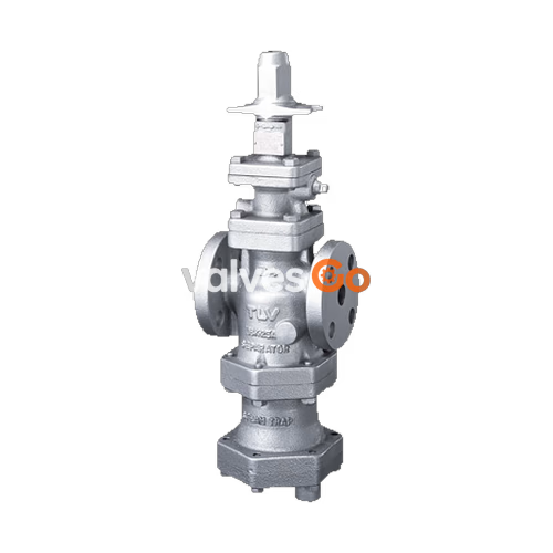
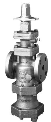
TLV COS-3, COS-16, and COS-21 (along with the COSR series) are technologically advanced self-actuated steam pressure reducing valves. Steam-using equipment can perform its intended operation only when dry saturated steam is available. Steam containing entrained condensate, scale, or air not only reduces steam equipment productivity but also shortens the life of pressure reducing valves. The COS/COSR series helps eliminate these problems by supplying dry saturated steam at a constant pressure at all times. They combine a pressure reducing valve with a built-in cyclone condensate separator and a free float steam trap to provide accurate control and steam conditioning, maximizing process system performance.
| Model | COS-3 / COSR-3 | COS-16 / COSR-16 / COSR-16HT | COS-21 / COSR-21 |
|---|---|---|---|
| Primary Pressure Range | 0.1 to 0.3 MPaG (1 to 3 barg) | 0.2 to 1.6 MPaG (2 to 16 barg) | 1.35 to 2.1 MPaG (13.5 to 21 barg) |
| Secondary Pressure Adjustable Range | 0.01 to 0.05 MPaG (0.1 to 0.5 barg) | Within 10 to 84% of primary pressure (Min: 0.03 MPaG / 0.3 barg) | Within 10 to 84% of primary pressure (Min: 0.55 MPaG / 5.5 barg) |
| Pressure Differential | 0.07 to 0.85 MPaG (0.7 to 8.5 barg) | Max pressure differential of 0.85 MPa (8.5 bar) | Max pressure differential of 0.85 MPa (8.5 bar) |
| Minimum Adjustable Flow Rate | 5% of rated flow rate | 5% of rated flow rate (10% for sizes 65 mm and larger) | 5% of rated flow rate (10% for sizes 65 mm and larger) |
WARNING
To avoid malfunctions, product damage, accidents or serious injury, install properly and DO NOT use this product outside the specification range. Local regulations may restrict the use of this product to below the conditions quoted.
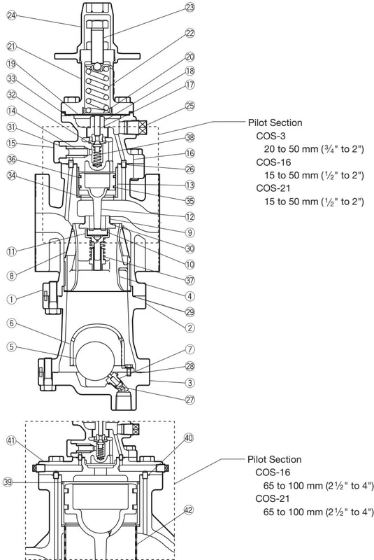
| No. | Description | Material |
|---|---|---|
| 1 | Main Body | Cast Iron / Ductile Cast Iron / Cast Stainless Steel |
| 2 | Trap Body | Same material as main body |
| 3 | Trap Cover | Same material as main body |
| 4 | Separator | Stainless Steel |
| 5 | Float | Stainless Steel |
| 6 | Float Cover | Same material as main body |
| 7 | Trap Valve Seat | Stainless Steel |
| 8 | Separator Screen | Stainless Steel |
| 9 | Main Valve Seat | Stainless Steel |
| 10 | Main Valve | Stainless Steel |
| 11 | Main Valve Holder | Stainless Steel |
| 12 | Piston | Stainless Steel |
| 13 | Cylinder | Stainless Steel |
| 14 | Pilot Screen | Stainless Steel |
| 16 | Pilot Body | Same material as main body |
| 17 | Pilot Valve | Stainless Steel |
| 18 | Pilot Valve Seat | Stainless Steel |
| 19 | Diaphragm | Stainless Steel |
| 22 | Coil Spring | Carbon Steel |
| 23 | Adjustment Screw | Cr-Mo Steel |
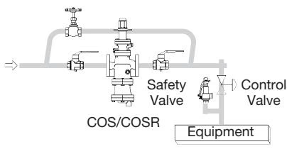
If the COS/COSR is installed either directly before or after an elbow or control valve, unevenness in flow may result in chattering and unstable pressure. To ensure stable steam flow, it is recommended that the COS/COSR be installed on straight runs of piping.
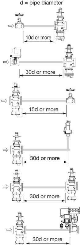
Inlet (primary side) of the COS/COSR:
Outlet (secondary side) of the COS/COSR:
A control valve (i.e. for temperature control) installed between the COS/COSR and the steam equipment may raise pressure between the COS/COSR and the control valve when the control valve is closed. Therefore, the control valve should be installed close to the steam-using equipment. A safety valve should be installed downstream of the control valve.
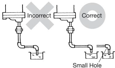
For ease of maintenance, installation of a union connection is recommended for the trap outlet pipe. Connect the outlet pipe to a condensate return line, or extend it to a trench. Make sure the end of the pipe is above the waterline to prevent dirt and water from being sucked up by the vacuum formed during trap closure.
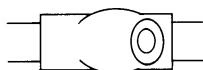
A strainer should be installed ahead of the COSR. The strainer should be 60 mesh or finer, but not so fine that it causes constriction of the flow area. The strainer should be installed horizontally and at 90° to its normal orientation to the pipeline, in order to prevent condensate accumulation in the screen body.
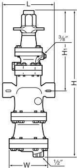
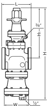
North American models are factory prepared for external sensing. An external sensing line MUST be installed. DO NOT SUPPLY STEAM until all piping and a 10 mm (3/8") secondary pressure sensing line with a slightly falling pitch have been properly installed.

DANGER
Keep the shutoff valve in the pressure sensing line open at all times during operation. If the shutoff valve is closed, COS/COSR will fully open and PRIMARY PRESSURE WILL BE SUPPLIED TO THE EQUIPMENT.
To ensure long service life, the following inspection and maintenance should be done regularly:
WARNING
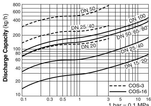
DO NOT use this product under conditions that exceed maximum differential pressure, as condensate backup will occur!
Explore similar products in our catalog




