PN25

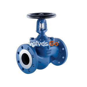
The TLV BE8H-16 is a durable bellows sealed globe valve for steam and water. It features a non-rotating stem, maintenance-free bellows seal, and stainless steel plug for reliable shut-off in industrial applications.
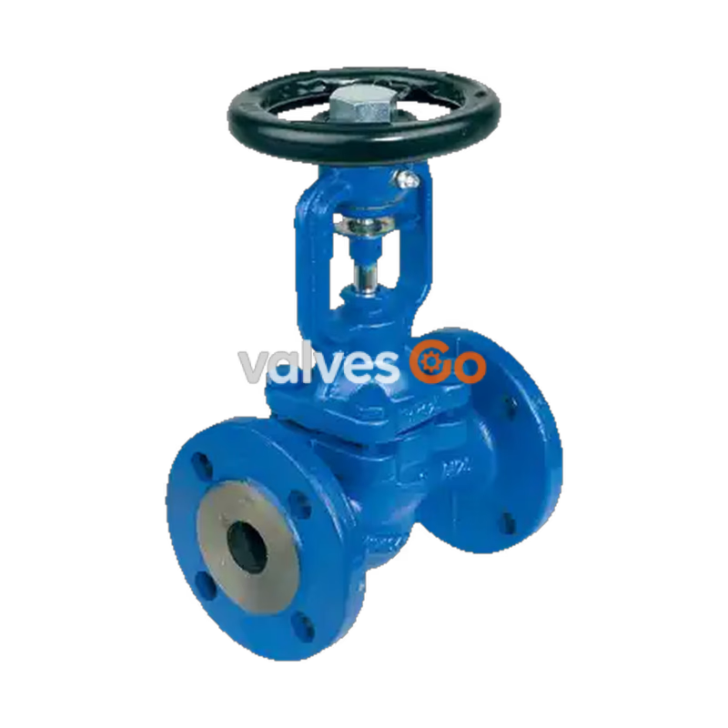
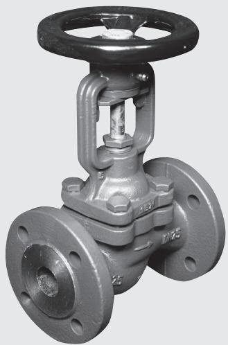
The TLV BE8H-16 is a bellows sealed globe valve with a flanged connection, designed for industrial systems handling steam, water, and other non-hazardous fluids. Its durable stem is protected by both a bellows seal and a secondary gland, ensuring exceptional leak-tightness and safety under demanding conditions.
The non-rotating stem and non-rising handwheel with position indication increase the valve's lifespan and make operation straightforward. Built with a stainless steel plug and seat ring, the BE8H series delivers reliable fluid shut-off across various piping systems.
WARNING
Do not use for toxic, flammable or otherwise hazardous fluids.
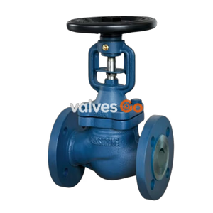
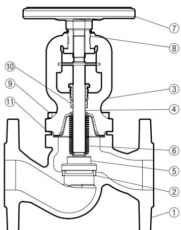
The valve consists of a body, seat ring, bonnet, stem, handwheel, gland, plug, and a flexible bellows.
The plant designer is responsible for the selection of a valve that is suitable for the specific working conditions.
| Model | BE8H-16 | BE8H-25 | BE8H-40 (Cast Steel) | BE8H-40 (Stainless Steel) |
|---|---|---|---|---|
| Body Material | Cast Iron EN-GJL-250 | Ductile Cast Iron EN-GJS-400-18-LT | Cast Steel GP240GH | Cast Stainless Steel G-X5CrNiMo19-11-2 |
| Connection | Flanged PN 16 | Flanged PN 25 | Flanged PN 40 | Flanged PN 40 |
| Size | DN 15 to 200 | DN 15 to 200 | DN 15 to 200 | DN 15 to 200 |
| Temp (°C) | -20 | -10 | 50 | 100 | 150 | 200 | 250 | 300 | 350 | 400 |
|---|---|---|---|---|---|---|---|---|---|---|
| BE8H-16 | — | 16 | 16 | 16 | 14.4 | 12.8 | 11.2 | 9.6 | — | — |
| BE8H-25 | — | 25 | 25 | 25 | 24.3 | 23 | 21.8 | 20 | 17.5 | — |
| BE8H-40 (Steel) | 30 | 40 | 40 | 37.1 | 35.2 | 33.3 | 30.4 | 27.6 | 25.7 | 23.8 |
| BE8H-40 (SS) | 40 | 40 | 40 | 40 | 36.3 | 33.7 | 31.8 | 29.7 | 28.5 | 27.4 |
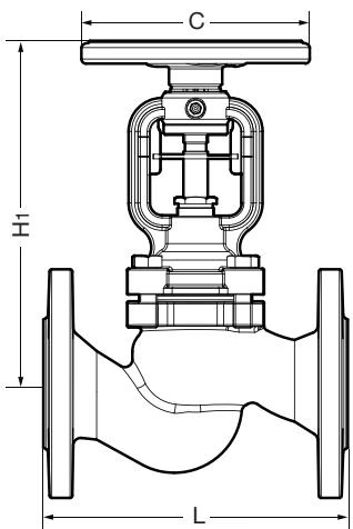
| Model | Value | DN 15 | DN 25 | DN 40 | DN 50 | DN 80 | DN 100 | DN 150 | DN 200 |
|---|---|---|---|---|---|---|---|---|---|
| BE8H-16 / 25 | Kvs (DIN) | 5.9 | 13 | 30 | 41 | 115 | 181 | 364 | 725 |
| BE8H-16 / 25 | Cv (US) | 6.9 | 15 | 35 | 48 | 134 | 211 | 425 | 846 |
| BE8H-40 | Kvs (DIN) | 6.0 | 15.5 | 28.8 | 46.5 | 113 | 180 | 358 | 552 |
| BE8H-40 | Cv (US) | 7.0 | 18 | 33.6 | 54.2 | 132 | 210 | 417 | 644 |
(Note: Extracted key sizes for readability. Refer to source datasheet for full DN range).
TIP
The valve can be installed in any position, however it is recommended to install it with the handwheel upwards.
| Fault | Possible Reason | Remedy |
|---|---|---|
| No flow | Valve closed | Open the valve |
| Flange dust caps were not removed | Remove dust caps on the flanges | |
| Poor flow | Valve is not open enough | Open the valve |
| Dirty filter / Clogged pipeline | Clean or replace the screen / Check the pipeline | |
| Difficulty operating the handwheel | Dry stem / Gland overtightened | Grease the stem / Slightly slacken gland nut |
| Stem leakage | Bellows damage | Tighten the gland until leakage stops and replace the upper part of the valve |
| Seat leakage | Incorrect shut off | Tighten the handwheel without using any auxiliary tools |
| Seat or disc damage | Replace the valve and contact the supplier |
Explore similar products in our catalog