Product Overview
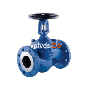
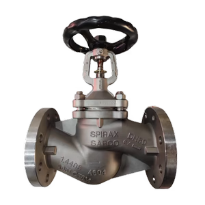
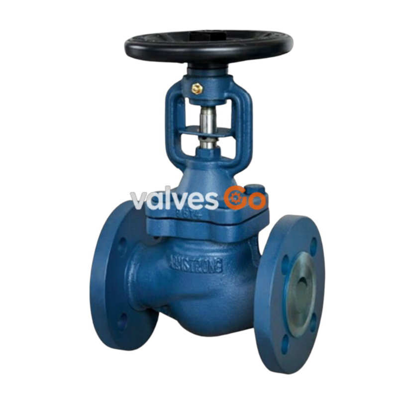
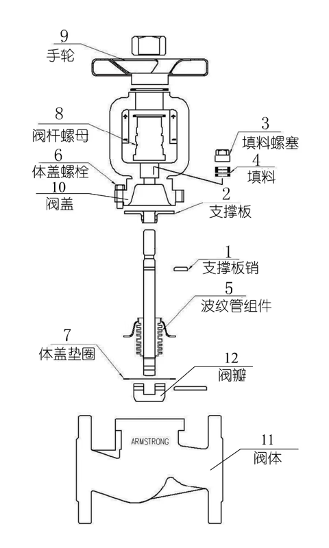
Armstrong BD16/BD25/BCS16/BCS25 Bellows Sealed Globe Valve is a key control component designed for industrial fluid systems. It features an advanced dual combination seal structure - using dual-wall stainless steel bellows as the main stem seal element, combined with graphite packing as secondary auxiliary seal, fundamentally eliminating media leakage and ensuring highly reliable dynamic and static sealing performance. The disc and seat are precision ground to form a flat sealing surface, ensuring long-term stable operation unaffected by stem movement. For high pressure or large diameter applications, the dual disc design significantly reduces opening/closing torque, effectively solving operation difficulties. The product covers multiple materials, pressure ratings and connection types to meet different industrial application requirements, making it an ideal choice for opening, flow control and shut-off in fluid pipelines.
Product Specifications
Basic Specification Table
| Model | Body Material | Pressure Rating | Connection Type | Nominal Diameter | Max Temp | Min Temp |
|---|
| BD16 | Ductile Iron | PN16 | Flange HG20592.RF | DN15-DN300 | 350°C | -10°C |
| BD25 | Ductile Iron | PN25 | Flange HG20592.RF | DN15-DN300 | 350°C | -10°C |
| BCS16 | Cast Steel | PN16 | Flange HG20592.RF | DN15-DN300 | 425°C | -29°C |
| BCS25 | Cast Steel | PN25 | Flange HG20592.RF | DN15-DN300 | 425°C | -29°C |
| BCS40 | Cast Steel | PN40 | Flange HG20592.RF | DN15-DN300 | 425°C | -29°C |
| BFS40 | Forged Steel | PN40 | Threaded/Socket Weld | DN15-DN50 | 425°C | -29°C |
Pressure-Temperature Operating Range (Bar)
BD Series
| Temp | 25°C | 100°C | 150°C | 200°C | 250°C | 300°C | 350°C |
|---|
| BD16 | 16 | 16 | 15.5 | 14.7 | 13.9 | 12.8 | 11.2 |
| BD25 | 25 | 25 | 24.3 | 23 | 21.8 | 20 | 17.5 |
BCS/BFS Series
| Temp | -29~38°C | 93°C | 149°C | 204°C | 260°C | 315°C | 343°C | 371°C | 399°C | 425°C |
|---|
| BCS16 | 16 | 14 | 13 | 11 | 10 | 8 | 7 | 6 | 5 | 5 |
| BCS25 | 25 | 23 | 21 | 19 | 17 | 14 | 13 | 12 | 11 | 10 |
| BCS40 | 41 | 37 | 36 | 34 | 32 | 28 | 27 | 27 | 26 | 21 |
| BFS40 | 41 | 37 | 36 | 34 | 32 | 28 | 27 | 27 | 26 | 21 |
Installation Instructions
Pre-Installation Preparation
- Before installation, verify the product nameplate to confirm specifications match pipeline system requirements, and carefully read installation/maintenance instructions and related technical documentation.
- Inspect each valve for damage, especially rotate the stem to check for misalignment (stems are easily bent during transportation).
- Clean the pipeline to remove iron oxide scale, sand, welding slag and other debris using water flushing or compressed air blowing. When steam contains significant contaminants, install a temporary strainer upstream of the valve and remove after system cleaning is complete.
- Remove the protective cover from the flange, inspect the valve cavity, and clean any dirt by flushing or wiping with a clean soft cloth.
Installation Requirements
- Handwheel-operated bellows globe valves can be installed at any pipeline position, but should allow convenient operation and maintenance. Valves with worm gear actuators require adequate space for installation or removal.
- Products with nominal diameter DN50 (weight >24kg) and above require lifting equipment. Lifting ropes should be attached to the flange, never to the handwheel or stem, to avoid component damage.
- The valve cavity is asymmetrical - fluid must flow from bottom to top through the valve port (media does not press against packing when closed, facilitating maintenance). Install according to the flow direction marking on the valve; incorrect installation is strictly prohibited.
- Handwheel height should be at chest level (typically 1.2m from operating floor). Floor-mounted valve handwheels should face upward, avoiding tilting. Valves near walls or equipment should allow standing room for operators; overhead operation is prohibited (especially for acid, alkali, or toxic media pipelines).
- Do not install with handwheel facing downward to prevent media accumulation in the bonnet space causing stem corrosion, and to facilitate packing replacement. Underground installation is prohibited to prevent moisture corrosion of exposed stems.
- When installing flanged valves, tighten bolts symmetrically and evenly, ensuring valve flange is parallel to pipe flange with appropriate gap, avoiding excessive pressure that could cause cracking.
- Install a steam trap near the upstream of the valve to ensure timely discharge of upstream condensate when valve is closed, preventing water hammer damage.
- Open globe valves slowly to prevent system vibration.
Operation
- The valve opens and closes by rotating the handwheel to control media flow: rotate counterclockwise toward "+" to open, clockwise toward "-" to close.
- Apply force steadily during operation without impact. After fully opening, reverse the handwheel slightly to tighten threads and prevent loosening damage.
- Do not use excessive leverage to assist operation to avoid damaging valve components. Replace damaged or missing handwheels immediately; do not substitute with adjustable wrenches to prevent stem square damage causing operation failure.
- Some media cause valve components to contract when cooled after valve closure. Operators should re-close at appropriate times to ensure no gaps in sealing surfaces, preventing high-velocity media erosion.
- Opening and closing must be within limit device range. Never exceed bellows maximum extension or compression limits, as this will damage bellows causing seal failure.
Maintenance

Storage Requirements
Store valves in a dry, ventilated indoor location with dust covers on both ends of passages. Periodically inspect valves in long-term storage, focusing on keeping sealing surfaces clean and preventing damage.
Routine Maintenance
During use, regularly inject high-temperature grease into the valve grease fitting. Valves with worm gear actuators require periodic lubrication of the actuator.
Replacement of Wear Parts
Replacing Body-Bonnet Gasket
- Open the valve to the open position.
- Use a wrench to remove body-bonnet bolts one by one.
- Separate body and bonnet, remove old gasket, install new gasket (ensure gasket surface is clean and flat before replacement).
- Reinstall bonnet on body, install removed bolts, tighten diagonally and evenly (refer to recommended nut tightening torque values).
Replacing Packing
- Open the valve to the open position.
- Use a wrench to remove body-bonnet bolts one by one.
- Separate body and bonnet, remove support plate pin.
- Use wrench to loosen packing plug, rotate handwheel to remove bellows assembly.
- Unscrew packing plug, remove old packing, install new packing, screw in packing plug (do not tighten yet).
- Reinstall bellows assembly into stem nut, reinstall support plate pin.
- Rotate handwheel to fully open position, reinstall bonnet on body, tighten bolts diagonally and evenly.
- Rotate handwheel back and forth to move stem up and down several times, then use wrench to tighten packing plug.
Replacing Bellows
- Open the valve to the open position.
- Use a wrench to remove body-bonnet bolts one by one.
- Separate body and bonnet, remove support plate pin.
- Use wrench to loosen packing plug, rotate handwheel to remove bellows assembly.
- Take new bellows assembly, reinstall into stem nut, reinstall support plate pin.
- Rotate handwheel to fully open position, reinstall bonnet on body, tighten bolts diagonally and evenly.
- Rotate handwheel back and forth to move stem up and down several times, then use wrench to tighten packing plug.
Recommended Nut Tightening Torque
| DN Size | Bolt/Nut Size | Recommended Torque |
|---|
| DN15, DN20, DN25, DN32 | M10 | 45 N/M |
| DN40 | M12 | 65 N/M |
| DN65, DN80, DN100, DN125 | M16 | 165 N/M |
| DN150, DN200 | M18 | 190 N/M |
| DN250, DN300 | M24 | 235 N/M |
Troubleshooting
| Symptom | Cause | Solution |
|---|
| Difficult/stiff opening | Excessive force when closing, causing jamming | Avoid excessive force when closing, do not use oversized leverage |
| Internal leakage | Incorrect flow direction, eroding sealing surface | Reinstall according to flow direction arrow on body |
| Internal leakage | Sealing surface wear | Re-grind sealing surface |
| Internal leakage | Disc scratched or worn | Replace or re-grind disc |
| Internal leakage | Bent stem | Straighten or replace stem |
| External leakage at packing | Packing aging | Replace packing and bellows assembly |
| External leakage at packing | Bellows damaged | Replace bellows assembly |
| Valve failure | Small diameter valve blocked by debris | Disassemble and remove debris |
| Valve failure | Disc detached | Repair or replace disc |
| Valve failure | Internal thread damaged | Replace with corrosion-resistant stem; reduce operating force on small valves, replace promptly when damaged |
Applications
This product is suitable for opening, flow control and shut-off of fluids in various industrial pipeline systems. Applicable media include water, steam, oil and other non-corrosive fluids. Widely used in fluid transport pipelines in chemical, power, pharmaceutical, heating and other industries, especially suitable for demanding industrial environments with high sealing requirements and significant temperature fluctuations.