


PN25

TLV A-COSR-10 self-actuated air pressure reducing valve with shock-absorbing piston. Features ductile cast iron body, 0.1-0.9 MPaG primary pressure, and stainless steel internals.
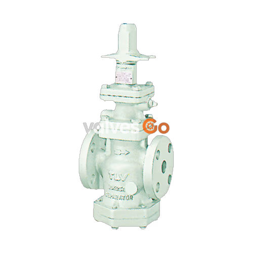
The TLV A-COSR-10 is a technologically advanced, self-actuated pressure reducing valve designed for accurate control in compressed air systems. It provides a more stable secondary pressure than conventional reducing valves and features a self-aligning shock-absorbing spherical piston. The A-COSR-10 is designed for long service life, with all major internal components made of stainless steel for superior durability.
| Parameter | Value |
|---|---|
| Model | A-COSR-10 |
| Body Material | Ductile Cast Iron (GGG40.3/EN 5.3103) / Cast Stainless Steel (A351/A351M Gr.CF8 or CF8M) |
| Connection | Flanged, DIN |
| Size | DN 15, 20, 25, 32, 40, 50 |
| Maximum Operating Pressure (PMO) | 9 barg (0.9 MPaG) |
| Maximum Operating Temperature (TMO) | 100 °C |
| Primary Pressure Range | 1 – 9 barg (0.1 - 0.9 MPaG) |
| Adjustable Pressure Range | 0.5 – 7 barg (0.05 - 0.7 MPaG) |
| Minimum Differential Pressure | 0.5 bar (0.05 MPa) |
| Minimum Adjustable Flow Rate | 10% of rated flow rate |
| Applicable Fluid | Air |
WARNING
Do not use for toxic, flammable or otherwise hazardous fluids. Install properly and DO NOT use this product outside the recommended operating pressure, temperature and other specification ranges. Use only under conditions in which no freeze-up will occur.
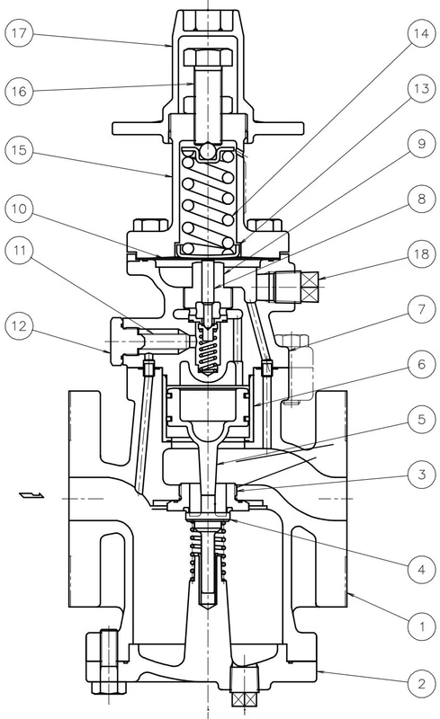
| No. | Name | No. | Name |
|---|---|---|---|
| 1 | Main Body | 10 | Diaphragm |
| 2 | Cover | 11 | Pilot Screen |
| 3 | Main Valve Seat | 12 | Pilot Screen Holder |
| 4 | Main Valve | 13 | Diaphragm Support |
| 5 | Piston | 14 | Coil Spring |
| 6 | Cylinder | 15 | Spring Housing |
| 7 | Pilot Valve Body | 16 | Adjustment Screw |
| 8 | Pilot Valve | 17 | Spanner Cap |
| 9 | Pilot Valve Seat | 18 | Plug – Sensing Line Port |
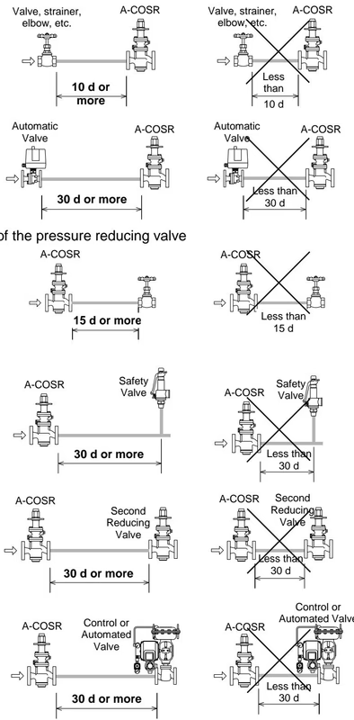
In order to ensure stable air flow, the piping upstream and downstream of the reducing valve must be straight runs. If a pressure reducing valve is installed either directly before or after an elbow or control valve, unevenness in air flow may result in chattering and unstable pressure.
Install the A-COSR vertically, so that the arrow mark on the body points horizontally in the direction of air flow. Allowable inclination is 10 degrees in the fore-aft direction and 15 degrees in the plane perpendicular to the air flow line.
Before installing the A-COSR, be sure to blow down all piping thoroughly. Blowdown is especially important for newly installed piping or after the system has been shut down for a long period of time.
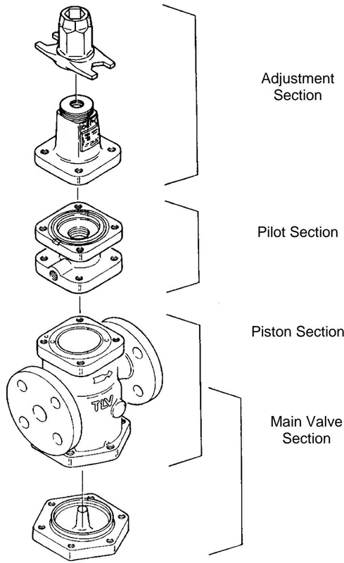
To ensure long service life, the following inspection and maintenance should be performed regularly:
| Part | Inspection and Maintenance Frequency |
|---|---|
| Pilot Screen | Disassemble and clean annually. If there is substantial blockage, install a strainer (approximately 60 mesh) ahead of the A-COSR. |
| Main Valve, Main Valve Seat, Pilot Valve and Pilot Valve Seat | Replace after approximately 15,000 hours. If there is chattering or dirt, premature wear may result. |
| Piston Ring | Replace after approximately 8,000 hours. If there is chattering or if scale build-up is severe, premature wear may result. |
| Piston | Replace after approximately 30,000 hours. If hunting or chattering takes place, premature wear may result. |
| Diaphragm | Replace after approximately 30,000 hours. If hunting or chattering takes place, cracks or fatigue may develop in a short period of time. |
| Problem | Symptom | Cause | Remedy |
|---|---|---|---|
| The secondary pressure does not rise | The pressure does not increase | No air is being supplied or the inlet valve is closed | Check the valves and pipings |
| The entrance to the screens or strainer is clogged | Clean or blow down | ||
| The secondary pressure cannot be adjusted or increases abnormally | Adjustment is difficult, and set pressure varies | The pilot screen is clogged | Clean |
| There is insufficient air flow | Check the flow, replace the A-COSR if necessary | ||
| The piston is clogged with dirt | Clean. Check the piston ring | ||
| The piston ring is worn | Replace with a new piston ring | ||
| There is a build-up of dirt on the sliding surfaces | Clean | ||
| Flow rate exceeds rated flow rate | Check the flow rate, replace with a larger size | ||
| The adjustment screw has seized | Replace with a new adjustment screw | ||
| The small hole on the piston is clogged | Clean | ||
| The diaphragm is distorted or damaged | Replace with a new diaphragm | ||
| Upon closing the valves on the secondary side, the secondary pressure abruptly rises | The bypass valve is leaking | Check, clean, and replace with a new valve if necessary | |
| There is a build-up of dirt on or damage to the pilot valve seat or main valve seat | Clean, Align, Replace if necessary | ||
| Hunting or chattering occurs | Occurs at low air demand | It is being operated below the lower flow rate limit | Check the volume of air supply, replace with a smaller diameter valve |
| Hunting never stops | There is too high a reduction ratio | Change within the specification range | |
| Chattering never stops | Condensate is contained, or the trap is blocked | Check the trap, Check the piping |
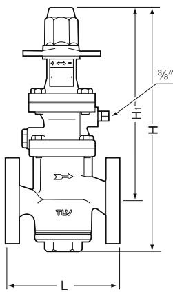
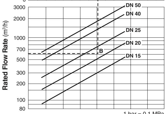
(Rated flow rates represent equivalent flow rates of air at 20 °C under atmospheric pressure. 1 bar = 0.1 MPa)
Explore similar products in our catalog




