Type 2032

BURKERT 333328 Type 2032 pneumatic diaphragm T-valve. Features 2" weld end connection, stainless steel body, advanced PTFE/EPDM diaphragm, and PPS actuator.
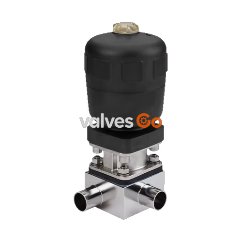
BURKERT 333328 Type 2032 is an externally controlled diaphragm T-valve consisting of a pneumatically operated piston actuator, a diaphragm, and a T-valve body. The proven and robust actuator with a plastic housing ensures use in hygienic or aggressive ambient conditions. The flow-efficient valve bodies with little dead space enable high flow rates and a wide range of possible uses. The actuator has a compact, autoclavable design (PPS variant).
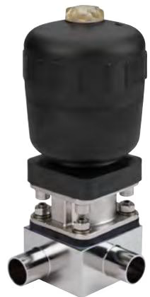
This specific model features a 2-inch weld end connection (ASME BPE), a stainless steel body, an advanced PTFE diaphragm with EPDM backing, and a PPS actuator. It operates with Control Function A (normally closed) and is rated for a medium pressure of 0 to 10 bar and temperatures from -5 °C to 143 °C.
| Symbol | Description |
|---|---|
| CF A | Control function A (CF A) Pneumatically operated T-valve Normally closed by spring force |
| CF B | Control function B (CF B) Pneumatically operated T-valve Normally opened by spring force |
| CF I | Control function I (CF I) Pneumatically operated T-valve on either side Switching position dependent on external control |
Actuator size 40…125
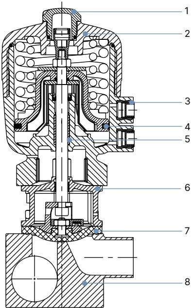
| No. | Element | Material |
|---|---|---|
| 1 | Transparent cap | Polysulfone PSU |
| 2 | Cover | Polyphenylene sulphide PPS (standard) Polyamide PA (on request) |
| 3 | Pilot air ports | Stainless steel 1.4305 |
| 4 | Piston seal | FKM |
| 5 | Socket | Sinter metal |
| 6 | Interface | Stainless steel 1.4404 |
| 7 | Diaphragm | EPDM (AD), PTFE/EPDM (EA), Advanced PTFE/EPDM (EU), laminate of GYLON® and EPDM (ER) |
| 8 | Valve body | Stainless steel |
T-Body with welded connection
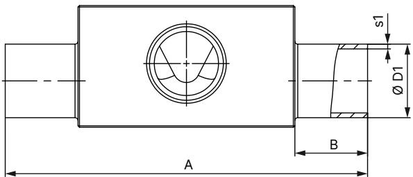
Dimensions in mm, unless otherwise stated. The following table shows the ASME BPE / DIN 11866 series C dimensions relevant to this 2-inch model family.
| Diaphragm size | Port 1 - Port 2 DN | ∅D1 | s1 | ∅D2 | s2 | A | B | C | E | F | G | H | I |
|---|---|---|---|---|---|---|---|---|---|---|---|---|---|
| 50 | 50...50 | 50.80 | 1.65 | 50.80 | 1.65 | 188.0 | 30 | 115.8 | 30 | 145 | 71 | 42 | 6.5 |
| 50 | 65...50 | 63.50 | 1.65 | 50.80 | 1.65 | 188.0 | 30 | 122.10 | 30 | 157 | 85 | 50 | 14.5 |
| 50 | 80...50 | 76.20 | 1.65 | 50.80 | 1.65 | 188.0 | 30 | 128.5 | 30 | 169 | 98 | 56 | 20.5 |
Maximum permissible operating pressure for control function A
TIP
For low operating pressures, optional variants with reduced spring force (EC04) are recommended. Pressure data [bar]: Overpressure to atmospheric pressure. Static: When closed, the valve is pressurised on one side with the maximum operating pressure.
| Diaphragm size | Actuator size ∅ | Pilot pressure [bar] | Maximum static operating pressure for EPDM, FKM [bar] | Maximum static operating pressure for PTFE, advanced PTFE, GYLON® [bar] |
|---|---|---|---|---|
| 8 | 40 (C) | 5.0...7 | 10 | 10 |
| 15 | 50 (D) | 5.0...7 | 10 | - |
| 15 | 63 (E) | 5.0...7 | 10 | 10 |
| 20 | 63 (E) | 5.5...7 | 10 | 10 |
| 20 | 80 (F) | 5.0...7 | 10 | 10 |
| 25 | 80 (F) | 5.5...7 | 10 | 10 |
| 40 | 100 (G) | 5.5...7 | 10 | 9 |
| 40 | 125 (H) | 5.5...7 | 10 | 10 |
| 50 | 125 (H) | 5.5...7 | 10 | 10 |
| 65 | 175 (K) | 5.0...6 | 10 | 6 |
| 80 | 175 (K) | 5.0...6 | 7 | 4 |
| 80 | 225 (L) | 5.0...6 | 10 | 10 |
| 100 | 225 (L) | 5.0...6 | 10 | 7 |
Installation for leakage detection One of the relief bores in the diaphragm bonnet for monitoring leakages must be at the lowest position.
Installation position Any installation position, preferably with the actuator facing up. For supply or removal of medium in circular pipelines, specific installation angles are recommended to ensure self-draining capabilities.
Explore similar products in our catalog