PN25

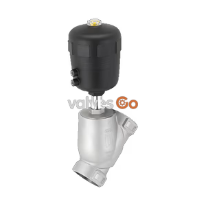
BURKERT 20122470 (Type 2961) manual globe control valve. DN 80 flange, stainless steel body, PTFE seal, 0-16 bar, -10 to 130°C. Features visual position indicator.
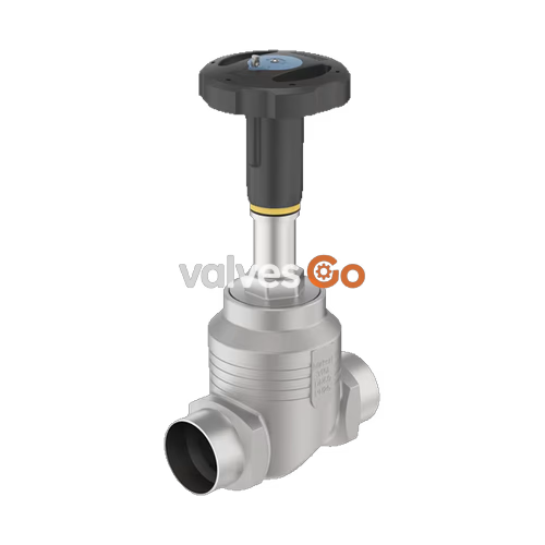
BURKERT 20122470 (Type 2961) is a manually operated 2-way globe control valve designed for excellent control accuracy under demanding operating conditions. It consists of a manual actuator and a globe valve body with exchangeable seats made of high-quality stainless steel. The precise spindle guide enables reliable control, while the soft PTFE seal guarantees tight shut-off. The actuator is made of high-quality plastic, features a visual position indicator, and can be optionally equipped with stroke limitation and locking.

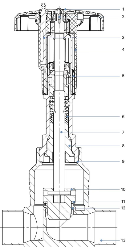
| No. | Element | Material |
|---|---|---|
| 1 | Cover | Polyamide (PA) |
| 2 | Screw | Stainless steel 1.4301 |
| 3 | Locking device | Stainless steel 1.4305 |
| 4 | Handwheel | Polyphenylene sulphide (PPS) |
| 5 | Visual position indicator with scale | Polyamide (PA) |
| 6 | Packing gland | PTFE V-rings (filled), with spring compensation |
| 7 | Stem | Stainless steel 1.4401 or 1.4404 |
| 8 | Spindle guide | Stainless steel 1.4404 (316L), PTFE filled |
| 9 | Housing seal | Graphite |
| 10 | Control cone | 1.4571 (optionally hardened) |
| 11 | Seat seal | PTFE or PEEK |
| 12 | Valve seat with O-ring | Stainless steel 1.4571, EPDM |
| 13 | Valve body | Stainless steel 316L/CF3M |
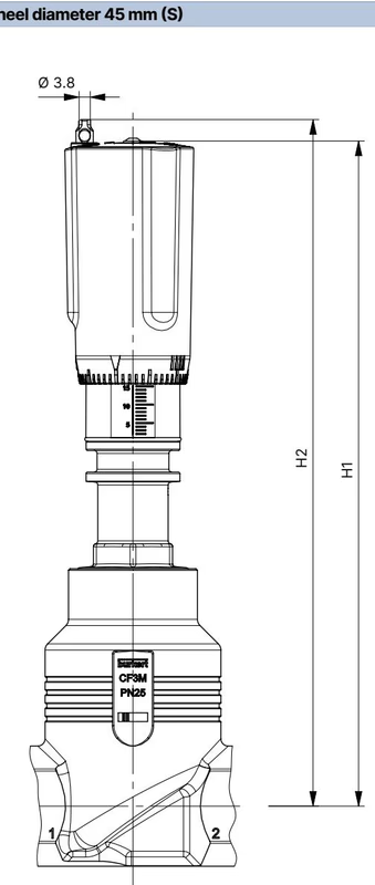
| Nominal connection size (pipe) DN | NPS | Handwheel diameter ∅ [mm] | H1 [mm] | H2 (locking) [mm] |
|---|---|---|---|---|
| 15 | 1/2 | 45 (S) | 217 | 224 |
| 20 | 3/4 | 45 (S) | 224 | 230 |
| 25 | 1 | 45 (S) | 228 | 234 |
| 32 | 1 1/4 | 110 (M) | 296 | 303 |
| 40 | 1 1/2 | 110 (M) | 301 | 307 |
| 50 | 2 | 110 (M) | 307 | 313 |
| 65 | 2 1/2 | 160 (L) | 361 | 368 |
| 80 | 3 | 160 (L) | 369 | 375 |
| 100 | 4 | 160 (L) | 379 | 385 |
Pressure and temperature restriction (derating) of the valve body (DIN EN 12516-1/PN25):
| Temperature [°C] | Operating pressure [bar] |
|---|---|
| -10...+50 | 25 |
| 100 | 24.5 |
| 150 | 22.4 |
| 200 | 20.3 |
| 230 | 19 |
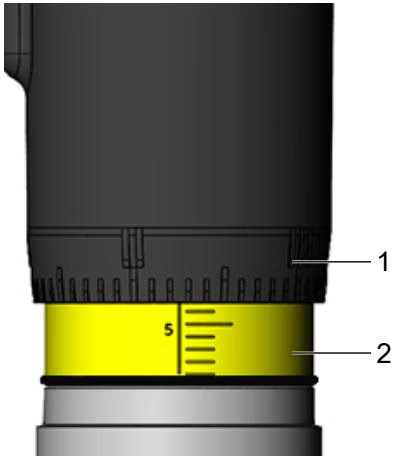
When turning the handwheel anticlockwise, the reproducible stroke scale becomes visible between the position indicator and the handwheel. The scale on the handwheel determines the rotation position of the handwheel (50 positions).
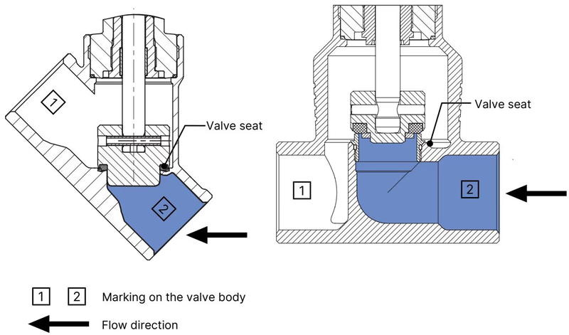
The valve seat is always closed against the medium flow. The flow direction should therefore be set such that the valve reaches the flow beneath the valve seat.
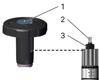
Both the minimum and the maximum position of the valve can be adjusted via an adjustment sleeve. The handwheel can be removed for this purpose.
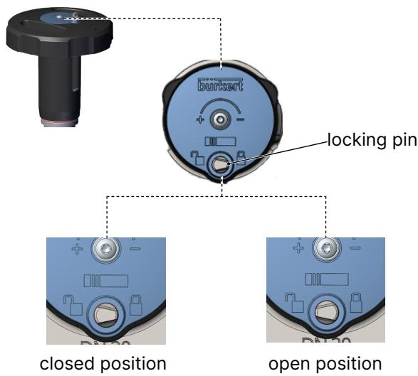
The valve can be secured against unintentional or unauthorized operation. A securing pin can be pressed down and turned. The locking pin has a hole (∅ 3.8) and can be secured with a padlock.
Explosion Hazard (For Ex variants)
Risk of injury due to high pressure and escaping medium
Risk of crushing by mechanically powered parts
Explore similar products in our catalog