Stainless Steel

Yoshitake WP-1 Shock Killer water hammer arrester. Features a compact brass body, 1.0 MPa max pressure, and maintenance-free operation for residential and commercial piping.
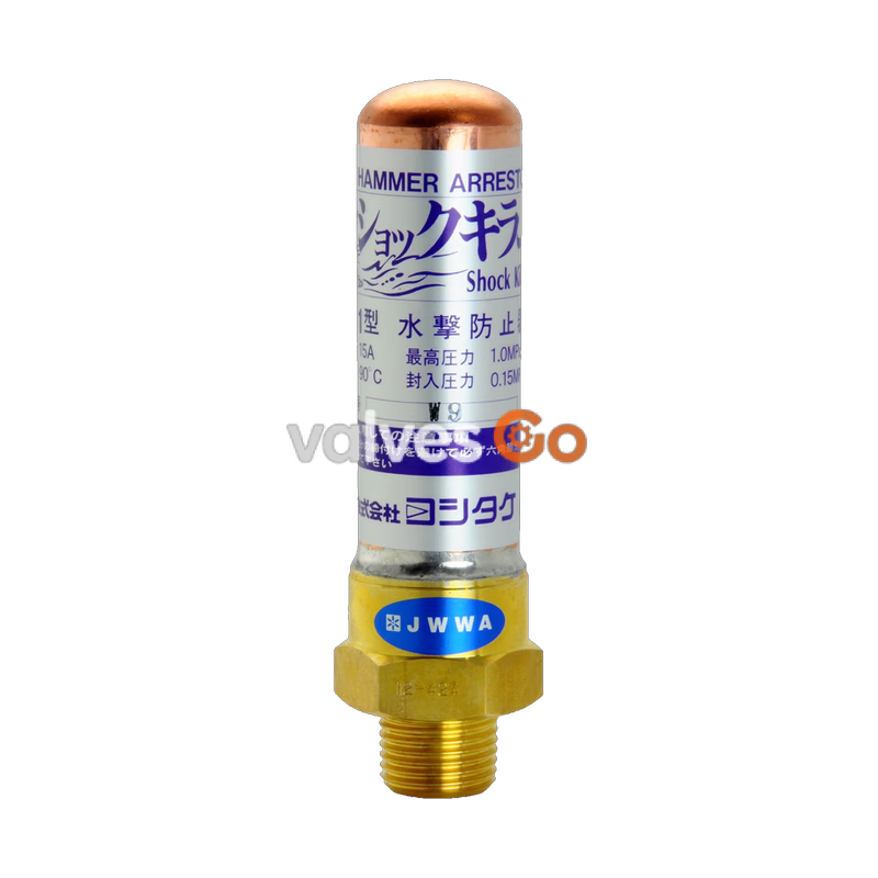
Yoshitake WP-1 Shock Killer water hammer arrester helps create a comfortable residential environment. Since complex housing and office buildings become higher and larger, the residential environment faces various threats, including noise caused by water hammer. Just a little carelessness can bring about damage to devices or disturbance of sleep. The WP-1 Shock Killer absorbs water hammer effectively and protects the piping system.
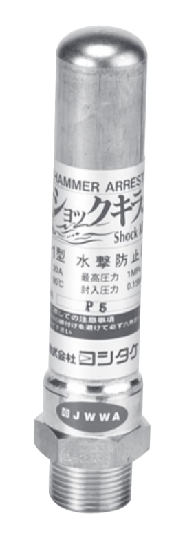
| Nominal size | 15A | 20A | 25A |
|---|---|---|---|
| Application | Cold and hot water, City water | Cold and hot water, City water | Cold and hot water, City water |
| Maximum pressure | 1.0 MPa | 1.0 MPa | 1.0 MPa |
| Maximum temperature | 90°C | 90°C | 90°C |
| Maximum flow velocity | 3 m/s | 3 m/s | 3 m/s |
| Material (Body) | Brass | Brass | Brass |
| Material (Pipe) | Copper | Copper | Copper |
| Connection | JIS R | JIS R | JIS R |
| Charged pressure | 0.15 MPa | 0.15 MPa | 0.15 MPa |
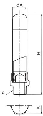
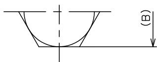
| Nominal size | d | H (mm) | A (mm) | B (mm) | Weight (kg) |
|---|---|---|---|---|---|
| 15A | R 1/2 | 123 | 28.3 | 32 | 0.25 |
| 20A | R 3/4 | 154 | 28.3 | 32 | 0.30 |
| 25A | R 1 | 182 | 34.8 | 41 | 0.50 |
The figures below show the difference in water hammer level between when the Shock Killer is used and not used.
Fig. 1 When the Shock Killer is not used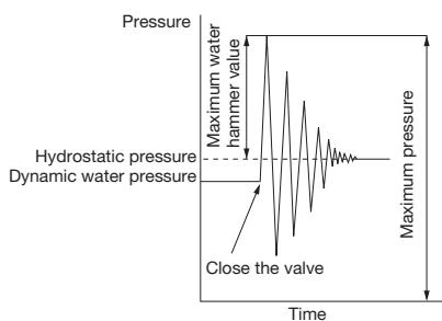
Fig. 2 When the Shock Killer is used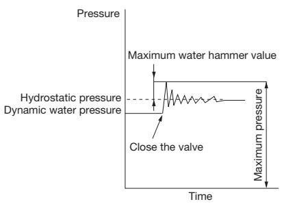
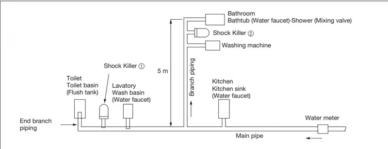
The Shock Killer is available mainly for the two applications below.
Note on Large Loads
If the units of load in total is over 60, use a proper number of 25A Shock Killers to fulfill the units of load.
Table-1 Unit of load for water supply devices (Excerpted from SHASE Handbook)
| Name of device | Faucet | Unit of load (Public use) | Unit of load (Private room) |
|---|---|---|---|
| Toilet basin | Flush valve | 10 | 6 |
| Toilet basin | Flush tank | 5 | 3 |
| Urinal | Flush valve | 5 | - |
| Urinal | Flush tank | 3 | - |
| Wash basin | Water faucet | 2 | 1 |
| Hand wash basin | Water faucet | 1 | 0.5 |
| Medical wash basin | Water faucet | 3 | - |
| Office sink | Water faucet | 3 | - |
| Kitchen sink | Water faucet | - | 3 |
| Cookery sink | Water faucet | 4 | 2 |
| Cookery sink | Mixing valve | 3 | - |
| Dishwashing sink | Water faucet | 5 | - |
| Multi-station sink | Water faucet | - | 3 |
| Vanity sink (per faucet) | Water faucet | 2 | - |
| Scrab sink | Water faucet | 4 | 3 |
| Bathtub | Water faucet | 4 | 2 |
| Shower | Mixing valve | 4 | 2 |
| Bathroom-Modular bath | Equipped with toilet basin with flush valve | - | 8 |
| Bathroom-Modular bath | Equipped with toilet basin with flush tank | - | 6 |
| Drinking water fountain | Drinking water faucet | 2 | 1 |
| Water heater | Ball tap | 2 | - |
| Sprinkler-garage | Water faucet | 5 | - |
Hot Water Tap Adjustment
When a hot water tap is also used, the unit of load for a water supply device to a tap shall be 3/4 of the appropriate value shown in the table above.
Table-2 Nominal size selection table
| Total units of load for water supply devices | Nominal size |
|---|---|
| 1-11 | 15A |
| 12-32 | 20A |
| 33-60 | 25A |
| No. | Name of Parts | Material | Q.TY |
|---|---|---|---|
| 1 | Body | Brass (C3531) | 1 |
| 2 | Pipe | Copper (C1220) | 1 |
| 3 | Piston | Brass (C3531) | 1 |
| 4 | O Ring | NBR | 2 |
| 5 | Label | Polyester | 1 |
| 6 | Disc | NBR | 1 |
| 7 | Label | Polyester | 1 |
Yoshitake Piping Accessories
BJ, ES, MS, and YS series piping accessories for connection, expansion, and installation in fluid systems.
Explore similar products in our catalog