Stainless Steel

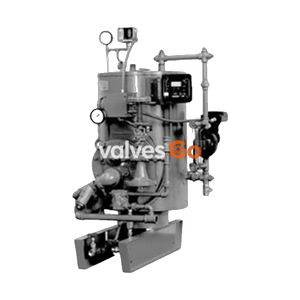
Armstrong CC Series Condensate Coolers mix hot condensate with cold water to safely reduce discharge temperatures to meet city and state codes. Available in 5 to 40 gpm capacities.
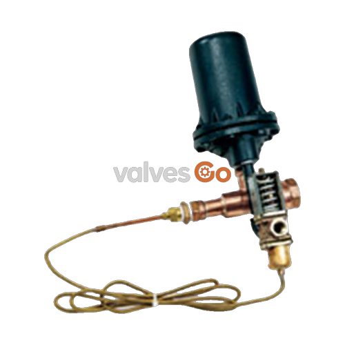
Armstrong CC Series Condensate Cooler is a device that mixes hot condensate or hot water with a cold water supply to reduce the temperature to acceptable discharge drain temperatures as required by city and state codes. It is a pre-assembled package that is suitable for any plumbing system. When hot condensate or hot water is drained into the condensate cooler body, the tempering valve opens and allows cold water to enter the chamber and mix with hotter liquid, cooling it to a preset temperature level of 135°F (57°C) or to a desired field set temperature.
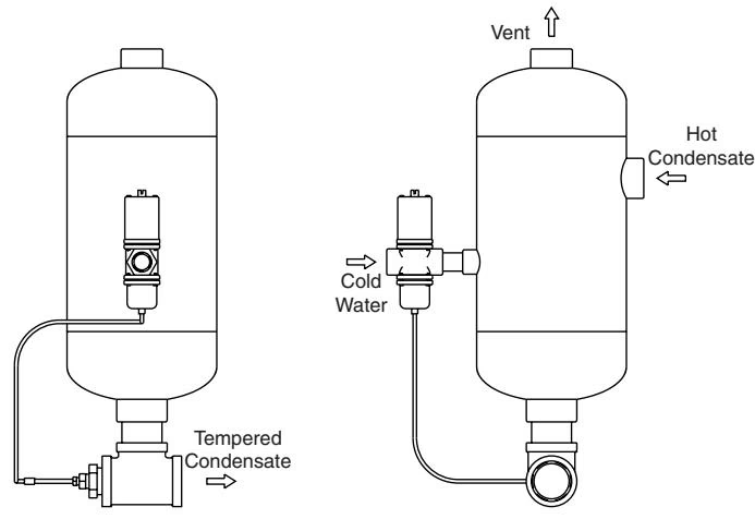
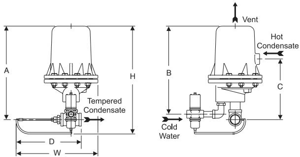 Model CC-5 and CC-12
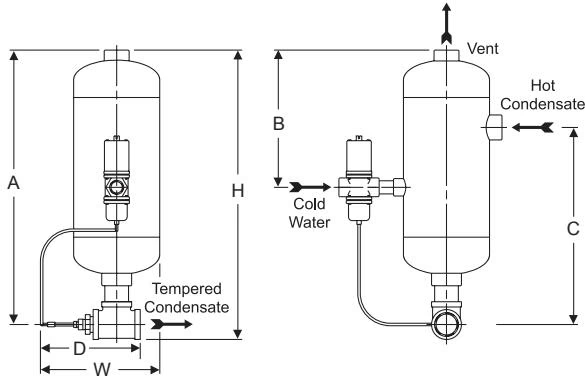 Model CC-25 and CC-40
Application Note
The cooler can also be used with heat exchangers or any application that requires the hot water or condensate temperature to be tempered.
Important Installation Notice
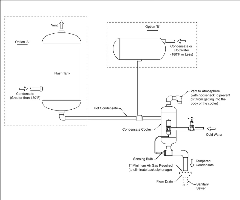
The condensate receiver should not be used as a flash tank. Condensate should be flashed prior to entering the condensate cooler. When using this device to cool hot condensate, it is required to vent all flash steam prior to piping into the body of the cooler. The body and vent of the cooler are not sized to be a flash tank.
Capacities represent the total of condensate and cooling water combined:
To determine the condensate load, use the following formula:
((B - C) / (H - C)) × Model = gallons of hot liquid or condensate
Where:
Example: ((135 - 50) / (180 - 50)) × 5 (CC-5) = 3.25 gpm 3.25 gal × 8.33 lbs per gallon × 60 = 1,624 lbs per hour.
Note: In the example, Model CC-5 (5 gpm) can handle 3.25 gpm of 180°F liquid. If cold water temperature or discharge temperature changes, the capacity will change.
| Component | Material |
|---|---|
| Body (CC-5 and CC-12) | ASTM A48 cast iron |
| Body (CC-25 and CC-40) | Carbon steel |
| Pipe and Fittings | Malleable iron |
| Body (Controller) | Brass |
| Sensing Bulb | Bronze |
| Dimension / Model | CC-5 | CC-12 | CC-25 | CC-40 |
|---|---|---|---|---|
| Vent | 3/4" (20 mm) | 1-1/2" (40 mm) | 1-1/2" (40 mm) | 2" (50 mm) |
| Hot Condensate Inlet | 3/4" (20 mm) | 1-1/2" (40 mm) | 1-1/2" (40 mm) | 2" (50 mm) |
| Tempered Condensate Outlet | 1-1/4" (32 mm) | 1-1/2" (40 mm) | 2" (50 mm) | 2-1/2" (65 mm) |
| Cold Water Inlet | 3/8" (10 mm) | 3/4" (20 mm) | 1" (25 mm) | 1" (25 mm) |
| "H" | 13" (330 mm) | 23" (584 mm) | 29" (737 mm) | 32-13/16" (833 mm) |
| "W" | 12-1/2" (318 mm) | 14-3/16" (361 mm) | 13" (330 mm) | 14-1/2" (368 mm) |
| "A" | 10-13/16" (275 mm) | 20-5/16" (516 mm) | 27-1/2" (698 mm) | 31" (787 mm) |
| "B" | 9-1/2" (241 mm) | 19-3/16" (487 mm) | 13-13/16" (351 mm) | 15-5/16" (389 mm) |
| "C" | 6-1/2" (165 mm) | 11-7/8" (302 mm) | 19-13/16" (503 mm) | 21-9/16" (548 mm) |
| "D" | 11" (279 mm) | 11" (279 mm) | 11" (279 mm) | 12" (305 mm) |
| Weight | 15 lb (6.8 kg) | 77 lb (35 kg) | 81 lb (37 kg) | 93 lb (42 kg) |
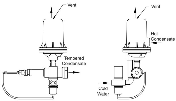 Models CC-5 and CC-12 Dimensions
 Models CC-25 and CC-40 Dimensions
| Problem | Cause | Solutions |
|---|---|---|
| Cannot get down to desired set temperature | Capacity of hot liquid greater than model can handle | Check with Armstrong for other options or models. Check your application with the given formula to check capacity based on any changing variables. |
| Cannot get down to desired set temperature | Cold water temperature is too hot | Verify seasonal changes and adjust if possible. |
| Cannot get down to desired set temperature | Cold water pressure is too low | Adjust pressure. |
| Cannot get down to desired set temperature | Cold water piping is too small | Increase pipe sizes. |
| Discharge Temperature Unstable | Thermal element of the tempering valve is faulty | Install new tempering valve. |