Ductile Cast Iron
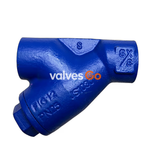
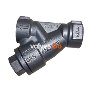
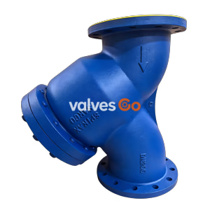
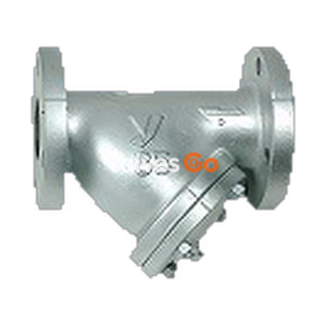
Yoshitake SY-5 Strainer is suitable for steam, air, hot/cold water, oil, and other non-hazardous fluids. Widely installed upstream of pressure reducing valves, temperature control valves, and other valves to protect equipment. Compact, lightweight, and economical with enlarged filtration area to reduce clogging impact. Features ductile cast iron body and stainless steel screen, JIS Rc threaded connection, nominal diameter range 10A-50A, meeting various pipeline filtration needs.
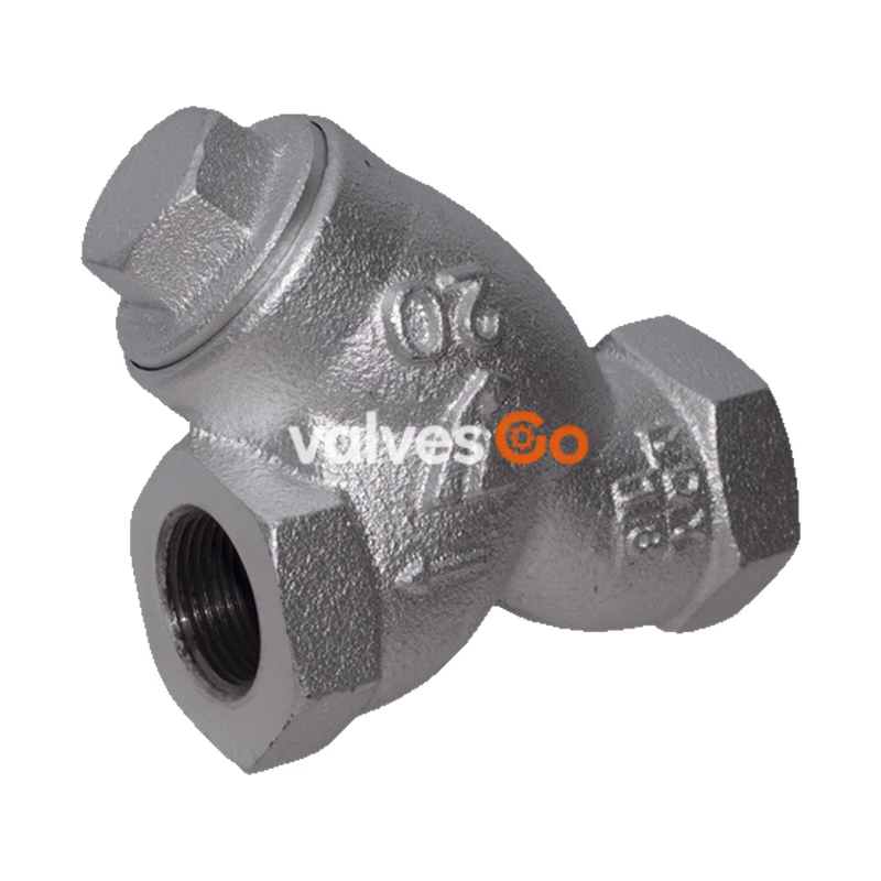
Yoshitake SY-5 Strainer is an economical filtration device designed for dust removal needs in various piping systems. It is especially suitable for installation upstream of pressure reducing valves, temperature control valves, solenoid valves, steam traps, and other valves to extend downstream equipment lifespan from protection and maintenance perspectives. The product features wide application and compact, lightweight design, with enlarged filtration area to address flow reduction caused by clogging, ensuring smooth fluid passage.
| Parameter | Specification |
|---|---|
| Applicable Fluid | Steam, Air, Hot/Cold Water, Oil, Other Non-hazardous Fluids (SY-6 recommended for hot/cold water) |
| Max Pressure | 2.0 MPa |
| Max Temperature | 220°C |
| Body Material | Ductile Cast Iron |
| Screen Material | Stainless Steel |
| Standard Screen Spec | 80 mesh (hole count: 2.5-7.21 holes/cm²) |
| Customizable Mesh | 20-100 mesh |
| Customizable Hole Count | 1.2-23.8 holes/cm² |
| Connection Type | JIS Rc Threaded |
| Pressure Loss Control | Recommended below 0.1MPa |
| Nominal Diameter | Thread Spec (d) |
|---|---|
| 10A | Rc 3/8 |
| 15A | Rc 1/2 |
| 20A | Rc 3/4 |
| 25A | Rc 1 |
| 32A | Rc 1-1/4 |
| 40A | Rc 1-1/2 |
| 50A | Rc 2 |
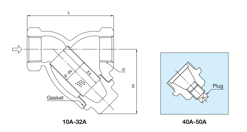
| Nominal Diameter | Thread Spec (d) | Length L (mm) | Height H1 (mm) | ds (mm) | ls (mm) | Gasket Spec (OD×ID×Thickness) | Plug Size | Weight (kg) |
|---|---|---|---|---|---|---|---|---|
| 10A | Rc 3/8 | 65 | 50 | 18 | 32 | φ30.5×φ24×1.0 | (R 1/4) | 0.4 |
| 15A | Rc 1/2 | 75 | 55 | 20 | 35 | φ34.5×φ26×1.0 | (R 1/4) | 0.6 |
| 20A | Rc 3/4 | 90 | 70 | 25 | 50 | ø41.5×326×1.0 | (Rc 3/8) | 0.9 |
| 25A | Rc 1 | 110 | 85 | 32 | 60 | φ50.5×φ40×1.0 | (R 3/8) | 1.4 |
| 32A | Rc 1-1/4 | 135 | 95 | 40 | 70 | φ61.5×φ50×1.0 | (R 3/8) | 2.2 |
| 40A | Rc 1-1/2 | 145 | 105 | 45 | 75 | φ67.5×φ55×1.0 | R 3/8 | 3.4 |
| 50A | Rc 2 | 170 | 120 | 56 | 90 | φ78.5×φ65×1.0 | R 3/8 | 4.5 |
Note
The SY-5 Strainer operates on a simple and efficient principle: fluid flows in from the strainer inlet side, passes through the stainless steel screen for filtration, where debris, iron slag, and other foreign matter are intercepted by the screen. The filtered clean fluid flows out from the outlet, protecting downstream piping and equipment from debris damage. By installing pressure gauges before and after the strainer, screen clogging can be determined based on pressure differential changes for timely cleaning and maintenance.
| Fluid | Description | Standard Velocity (m/s) |
|---|---|---|
| Saturated Steam | Vacuum or small diameter auxiliary pipes | 15 (10~20) |
| Saturated Steam | Large diameter | 30 (20~40) |
| Superheated Steam | Diameter φ75~250 | 40 (30~50) |
| Superheated Steam | High-grade material pipes | 70 (65~80) |
| Steam Coil Inlet | 0.3~0.7MPa | 30 (25~30) |
| Air | High pressure (above 1.0MPa) | 20 (20~25) |
| Air | Low pressure | 15 (5~15) |
| Air | Very low pressure (below 0.1MPa) | 10 (3~10) |
| Water, Oil | - | 2 (2~4) |
Note
The above table is based on JIS F7101 (Marine Engine Room Pipe Flow Velocity Standards). A safety factor of 20% above performance values is recommended for selection.
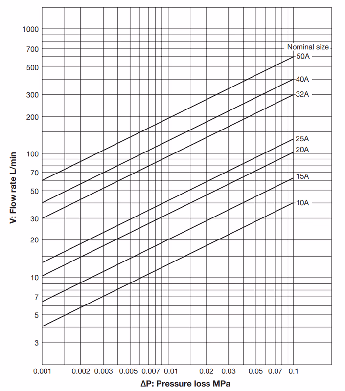
For the SY-5 Strainer (standard screen: 80 mesh, hole count 2.5-7.21 holes/cm²) with water as the fluid, refer to the product pressure loss chart for the relationship between pressure loss and flow rate. Different nominal diameters have different flow-pressure loss characteristics; consult based on actual application scenarios.
Warning
Precautions
Disassembly/Inspection Warning
Before disassembly and inspection, internal pressure in the product, piping, and equipment must be completely released. If fluid is at high temperature, allow cooling before work to avoid injury or burns from residual pressure.
Precautions