PN16
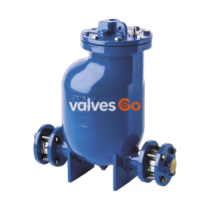
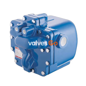
Yoshitake PF-7000 mechanical pumping trap. Steam or air-driven with no electricity required. Features a ductile cast iron body, 180°C max temperature, and 0.8 MPa driving pressure for efficient condensate transfer.
Yoshitake PF-7000 is a high-performance mechanical pumping trap designed for condensate recovery in industrial steam systems. Utilizing steam or air pressure as the driving force, it eliminates the need for electrical components and motors, making it suitable for hazardous environments and energy-saving applications. Its automated operation ensures efficient condensate transfer from receiver tanks to recovery lines with minimal running costs.
| Item | Specification |
|---|---|
| Model | PF-7000 |
| Nominal Size | 25A, 40A, 50A, 80A |
| Max. Driving Pressure | 0.8 MPa |
| Max. Temperature | 180°C |
| Motive Fluid | Steam or Compressed Air |
| Body Material | Ductile Cast Iron (FCD450) |
| Internal Trim | Stainless Steel |
INFO
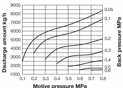
The most appropriate driving pressure is typically the back pressure at the outlet side plus 0.1 to 0.2 MPa. For sizes 25A to 50A, the inlet and outlet sizes match the nominal size; for 80A, the inlet is 80A and the outlet is 50A.
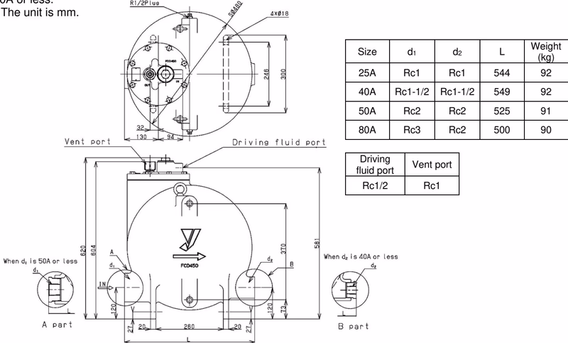
| Size | d1 (Inlet) | d2 (Outlet) | L (Height) | Weight (kg) |
|---|---|---|---|---|
| 25A | Rc 1 | Rc 1 | 544 | 92 |
| 40A | Rc 1-1/2 | Rc 1-1/2 | 549 | 92 |
| 50A | Rc 2 | Rc 2 | 525 | 91 |
| 80A | Rc 3 | Rc 2 | 500 | 90 |
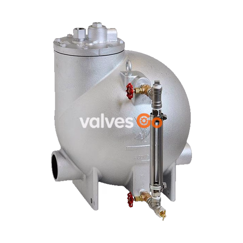
Note: Motive fluid port is Rc 1/2; Vent port is Rc 1.
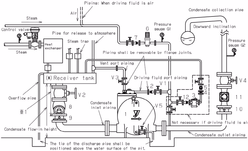
Proper piping is critical for optimal performance. The PF-7000 requires external check valves (typically SCV-2 or SCV-3) at both the inlet and outlet.
WARNING
Condensate may blow out from the vent port if driving pressure drops or fails. Always pipe the vent port to a safe location.
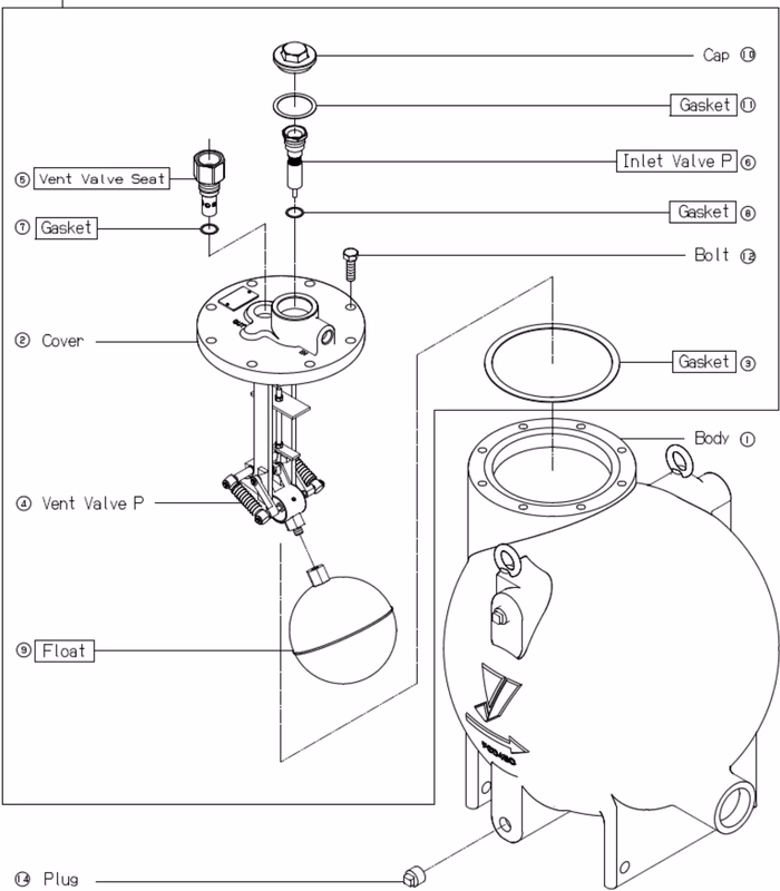
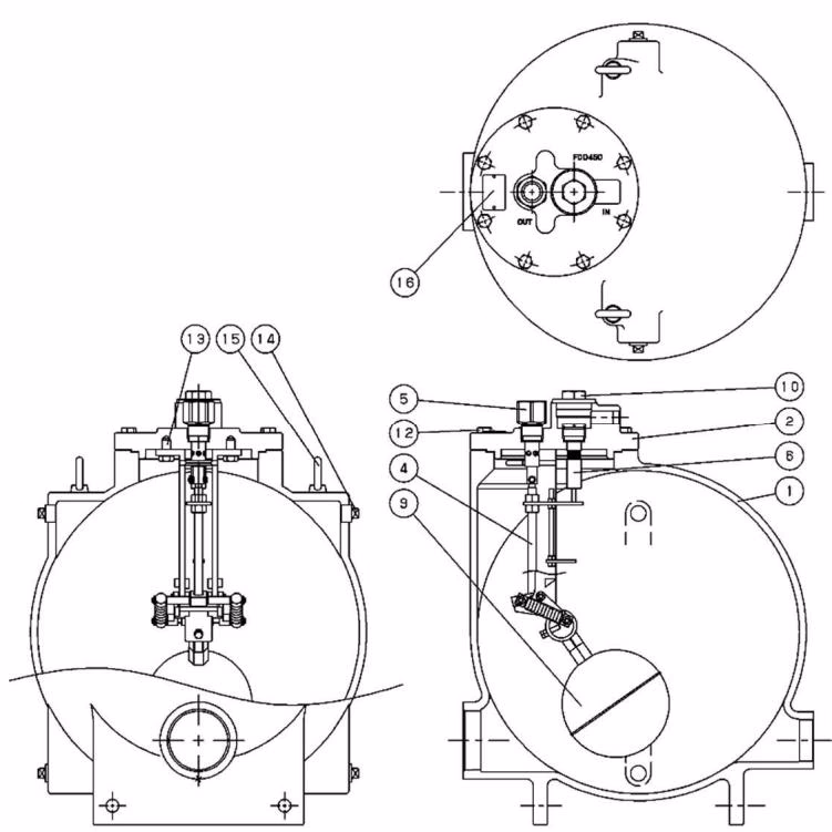
Regular inspection is recommended to ensure long-term reliability. Consumable parts including the vent valve P [4], inlet valve P [6], and float [9] should be inspected every 2 years or 120,000 cycles.
Explore similar products in our catalog