Feed-Forward Design

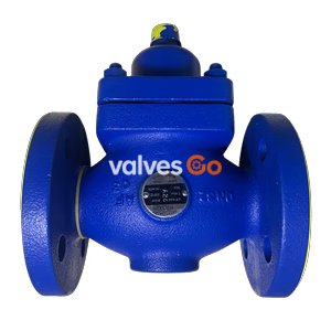
Yoshitake OB-4 and OB-4G direct acting temperature regulator valves for cooling applications. Features a dual-valve structure, cast iron body, JIS 10K FF flanged connection, and handles temperatures up to 180°C.
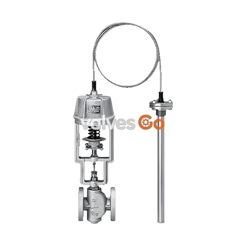
Yoshitake OB-4 and OB-4G are direct acting temperature regulator valves designed specifically for cooling applications. They are widely utilized in systems for ocean vessels, industrial plants, air conditioning equipment, and the chemical industry to accurately adjust cooling temperatures.
These temperature regulators feature a dual-valve structure, providing a larger flow rate compared to single-valve models. They are equipped with an adjusting handle, eliminating the need for special tools and allowing for easy temperature adjustment. The OB-4G model incorporates an external pressure type bellows, ensuring distinguished temperature resistance. Excellent accuracy is maintained since special packing is used for the spindle gland packing, which affects the opening and closing operation of the valve.
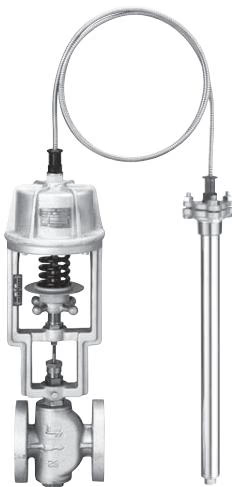
Related Models
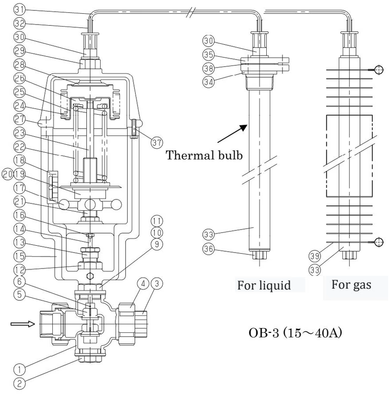
The shared operation manual for this series also covers the OB-3 and OB-3G models (JIS Rc screwed connections, bronze body, 15-40A). The specifications below focus on the primary OB-4 and OB-4G flanged models.
| Model | OB-4 | OB-4G |
|---|---|---|
| Nominal size | 15-150A | 15-125A |
| Application (Heating) | Cold water, Refrigerant | Cold water, Refrigerant |
| Application (Heated) | Cold and hot water, Oil, Non-dangerous fluid | Cold and hot water, Oil, Non-dangerous fluid |
| Max. pressure (Body) | 15-40A: 0.7 MPa [1.0 MPa] 50A: 0.5 MPa [0.7 MPa] 65A: 0.5 MPa [0.7 MPa] 80A: 0.4 MPa [0.5 MPa] 100A: 0.4 MPa 125A: 0.2 MPa [0.35 MPa for OB-4] 150A: 0.2 MPa | 15-40A: 0.7 MPa [1.0 MPa] 50A: 0.5 MPa [0.7 MPa] 65A: 0.5 MPa [0.7 MPa] 80A: 0.4 MPa [0.5 MPa] 100A: 0.4 MPa 125A: 0.2 MPa |
| Max. pressure (Thermal bulb) | 1.0 MPa | 1.0 MPa |
| Maximum temperature | 180°C | 180°C |
| Temperature adjusting range | 40-120°C (For liquid/air) | 15-100°C (For liquid/air) |
| Ambient temperature | Set temp. -10°C or less | Set temp. +30°C or less |
| Material (Body) | Cast iron | Cast iron |
| Material (Valve, valve seat) | Bronze (Stainless steel) | Bronze (Stainless steel) |
| Material (Valve spindle) | Stainless steel | Stainless steel |
| Material (Bellows) | Phosphor bronze | Phosphor bronze |
| Material (Thermal bulb) | Stainless steel (with fin for air) | Stainless steel (with fin for air) |
| Standard capillary length | 15-80A: 2 m 100-150A: 3 m | 15-80A: 2 m 100-125A: 3 m |
| Connection | JIS 10K FF flanged | JIS 10K FF flanged |
Note: If the ambient temperature is higher than the set temperature or less than 40°C, use the OB-4G (with external pressure type bellows). Available with capillary of up to 5 meters. Available with thermal well (SUS304 made or with a PTFE cap) for liquid.
The term "Withstand temperature" means the temperature from pressure resistance of the bellows.
OB-4
| Temperature adjusting range (°C) | Withstand temperature (°C) |
|---|---|
| 40-60 | 70 |
| 50-70 | 80 |
| 60-80 | 90 |
| 80-100 | 110 |
| 100-120 | 130 |
OB-4G
| Temperature adjusting range (°C) | Withstand temperature (°C) |
|---|---|
| 15-35 | 50 |
| 20-40 | 50 |
| 35-55 | 70 |
| 40-60 | 90 |
| 50-70 | 100 |
| 60-80 | 110 |
| 70-90 | 120 |
| 80-100 | 130 |
Depending on capillary length. The preset temperature error is the maximum temperature width ranging from the time when the valve closes until the time when the valve starts to open, not the value expressing the control width.
| Standard capillary length | OB-4 (Liquid) | OB-4 (Air) | OB-4G (Liquid/Air) |
|---|---|---|---|
| 2m | ± 2°C | ± 3°C | ± 3.5°C |
| 2-3.5m | ± 2.5°C | ± 3.5°C | ± 4°C |
| 3.5-5m | ± 3°C | ± 4°C | ± 4.5°C |
| (If the preset temperature is higher than 100°C, add ± 1.0°C) |
| Nominal size | 15A | 20A | 25A | 32A | 40A | 50A | 65A | 80A | 100A | 125A | 150A |
|---|---|---|---|---|---|---|---|---|---|---|---|
| OB-4 | 2 | 2 | 4 | 7 | 10 | 14 | 21 | 27 | 42 | 72 | 94 |
| OB-4G | 2 | 2 | 4 | 7 | 10 | 14 | 21 | 27 | 42 | 72 | — |
Unit: water (L/h). Measured under the condition of 0.5 MPa or max pressure at the temperature of "set temperature - 5°C" for cooling.
| Nominal size | 15A | 20A | 25A | 32A | 40A | 50A | 65A | 80A | 100A | 125A | 150A |
|---|---|---|---|---|---|---|---|---|---|---|---|
| OB-4 | 1.5 | 1.5 | 1.8 | 2.4 | 3.0 | 3.6 | 4.8 | 6.0 | 7.2 | 9.0 | 10.8 |
| OB-4G | 1.5 | 1.5 | 1.8 | 2.4 | 3.0 | 3.6 | 4.8 | 6.0 | 7.2 | 9.0 | — |
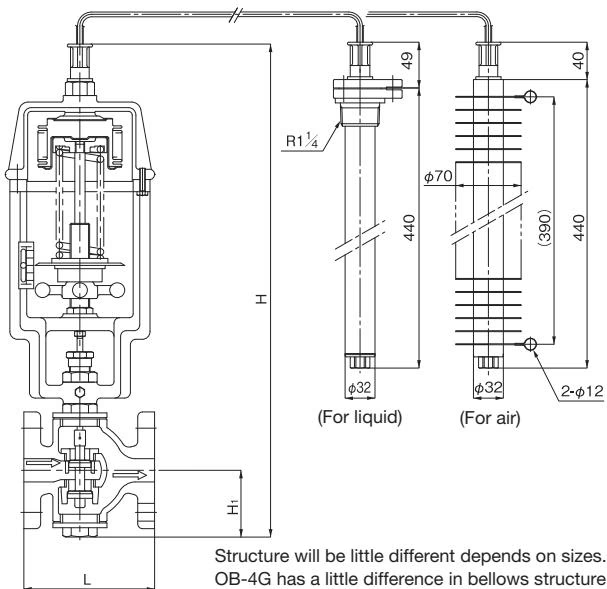
Structure will be a little different depending on sizes. OB-4G has a little difference in bellows structure.
| Nominal size | L (mm) | H1 (mm) | H (mm) | Weight (kg) |
|---|---|---|---|---|
| 15A | 126 | 60 | 520 | 15 |
| 20A | 130 | 60 | 520 | 16 |
| 25A | 140 | 70 | 540 | 18 |
| 32A | 150 | 75 | 550 | 21 |
| 40A | 160 | 75 | 550 | 23 |
| 50A | 180 | 110 | 620 | 29 |
| 65A | 215 | 125 | 650 | 38 |
| 80A | 260 | 135 | 670 | 48 |
| 100A | 300 | 160 | 750 | 58 |
| 125A | 360 | 190 | 810 | 76 |
| 150A (OB-4 only) | 382 | 220 | 980 | 125 |
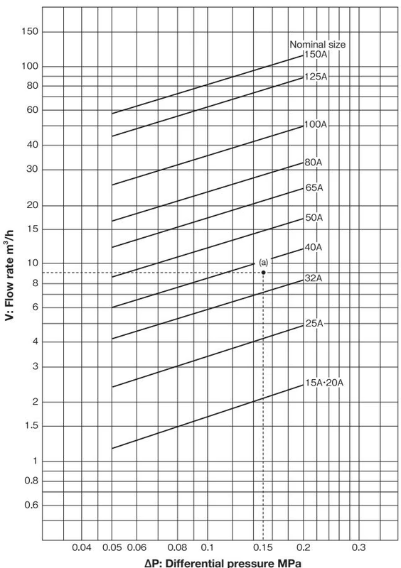
How to use the chart: When inlet pressure is 0.3 MPa, outlet pressure is 0.15 MPa, and flow rate is 9 m³/h, first find the intersection point (a) with the differential pressure (ΔP) 0.15 MPa (0.3 MPa – 0.15 MPa) before and after the valve and the flow rate 9 m³/h. Since this intersection point (a) locates between nominal sizes 32A and 40A, select the larger one, 40A. (Chart of the flow rate is a reference value.)
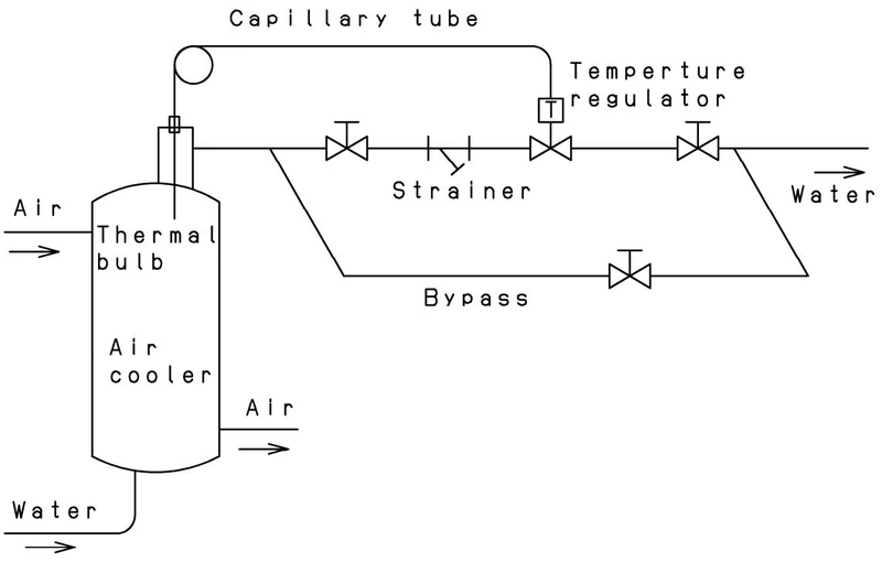
Installation Recommendations
Cautions
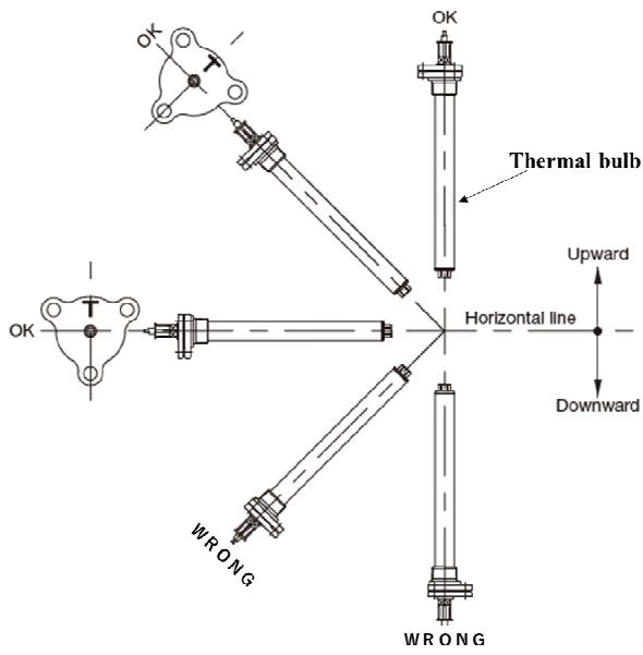
Make sure that more than 3/4 of its total length is in direct contact with the fluid to be heated. Install a thermal bulb in a posture in which the top of the thermal bulb is higher than the other side (connecting part to the tube), and in which the marking (on flange or nut) is always at the highest position.
| Trouble | Cause | Remedy |
|---|---|---|
| Temperature does not rise | 1. Inadequate adjustment. 2. Nominal size is too small. 3. Temperature range of sensor is not proper. 4. Ambient temperature is higher than preset. 5. Insufficient drainage from trap. | 1. Readjust. 2. Replace with proper size. 3. Replace the Upper part set. 4. Install ventilation to decrease ambient temp. 5. Open trap's bypass line. |
| Temperature rises excessively | 1. Inadequate adjustment. 2. Foreign substances stuck in main valve. 3. Leakage from bypass pipe. 4. Thermal bulb or bellows is damaged. | 1. Readjust. 2. Repair by factory is necessary. 3. Repair or replace. 4. Replace the Upper part set. |
| Large error of temperature control | 1. Spindle/guide do not move smoothly. 2. Bellows/valve shaft deformed. 3. Thermal bulb/thermometer in wrong positions. | 1. Disassemble and clean, or replace. 2. Replace the product. 3. Reinstall at points with best circulation. |
Yoshitake Control Valves / Self-operated Regulators
OB, GPR, CF, and GD series self-operated regulators for pressure and temperature control without external power.
Explore similar products in our catalog