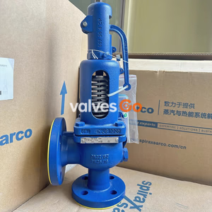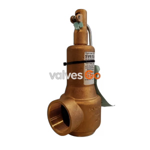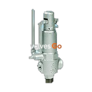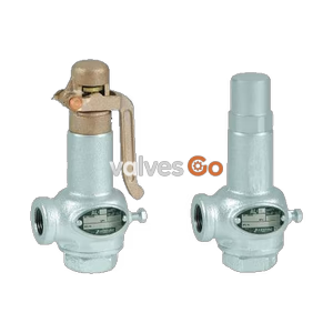
Lift Type

Yoshitake AL-31H lift type, closed safety relief valve in all stainless steel. Max set pressure 2.0 MPa. Ideal for steam, air, water, and oil.
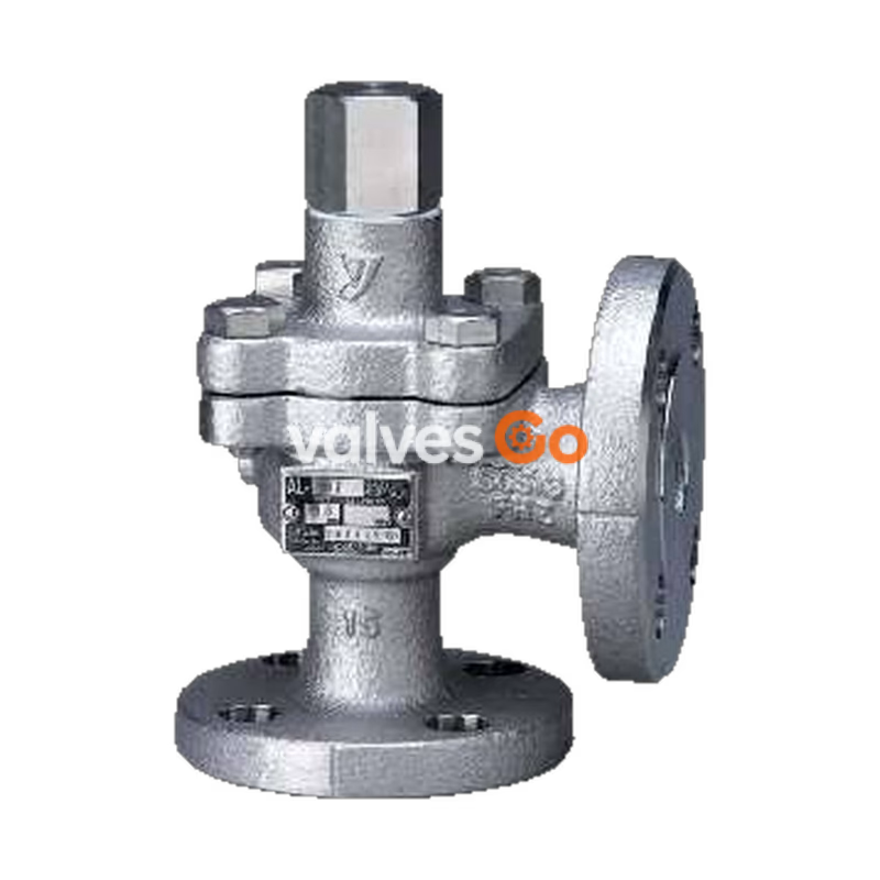
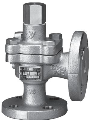
Yoshitake AL-31H is a lift type, closed safety relief valve made of all stainless steel, offering high corrosion resistance and durability. Designed to handle steam, air, cold and hot water, oil, and other non-dangerous fluids, this model can be set at a maximum pressure of 2.0 MPa.
| Model | AL-31H |
|---|---|
| Structure | Closed type * |
| Application | Steam, Air, Cold and hot water, Oil, Other non-dangerous fluids |
| Working pressure | 1.0 - 2.0 MPa |
| Maximum temperature | 220°C ** |
| Connection | JIS 16K RF flanged, JIS 20K RF flanged |
| Nominal size | 15 - 50A |
* The structure in which the fluid is discharged only from the outlet. ** The maximum temperature is 150°C when using for water, oil, or other liquids (the fluid is liquid).
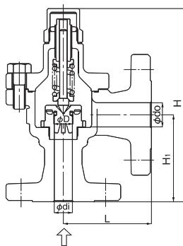
| Nominal size | Dimension (mm) di x D x do | L | H1 | H | Flow area (mm²) | Weight (kg) |
|---|---|---|---|---|---|---|
| 15A | 15 x 16 x 20 | 73 | 72 | 160 | 20.1 | 3.4 |
| 20A | 20 x 21 x 25 | 77 | 74 | 163 | 34.6 | 4.5 |
| 25A | 25 x 26 x 32 | 91 | 87 | 187 | 53.0 | 6.5 |
| 32A | 32 x 33 x 40 | 96 | 92 | 238 | 85.5 | 8.1 (8.3) |
| 40A | 40 x 41 x 50 | 114 | 100 | 277 | 132.0 | 11.4 (11.7) |
| 50A | 50 x 51 x 65 | 116 | 107 | 315 (357) | 204.2 | 15.0 (18.0) |
Capacity (Pressure vessel structure standard) [kg/h]
| Nominal size | Blowout area [mm²] | 1.0 MPa | 1.1 MPa | 1.2 MPa | 1.3 MPa | 1.4 MPa | 1.5 MPa | 1.6 MPa | 1.7 MPa | 1.8 MPa | 1.9 MPa | 2.0 MPa |
|---|---|---|---|---|---|---|---|---|---|---|---|---|
| 15A | 20.1 | 119 | 129 | 139 | 149 | 149 | 158 | 168 | 178 | 188 | 198 | 207 |
| 20A | 34.6 | 206 | 222 | 239 | 256 | 256 | 273 | 290 | 306 | 324 | 340 | 357 |
| 25A | 53.0 | 315 | 341 | 367 | 363 | 393 | 418 | 444 | 470 | 496 | 522 | 547 |
| 32A | 85.5 | 509 | 550 | 592 | 634 | 634 | 675 | 716 | 758 | 800 | 842 | 883 |
| 40A | 132.0 | 786 | 850 | 914 | 979 | 979 | 1042 | 1106 | 1171 | 1236 | 1300 | 1364 |
| 50A | 204.2 | 1216 | 1315 | 1414 | 1514 | 1514 | 1612 | 1712 | 1811 | 1912 | 2011 | 2110 |
Capacity (Pressure vessel structure standard) [kg/h]
| Nominal size | Blowout area [mm²] | 1.0 MPa | 1.1 MPa | 1.2 MPa | 1.3 MPa | 1.4 MPa | 1.5 MPa | 1.6 MPa | 1.7 MPa | 1.8 MPa | 1.9 MPa | 2.0 MPa |
|---|---|---|---|---|---|---|---|---|---|---|---|---|
| 15A | 20.1 | 181 | 197 | 214 | 230 | 247 | 264 | 280 | 297 | 313 | 330 | 347 |
| 20A | 34.6 | 311 | 340 | 368 | 397 | 426 | 454 | 483 | 511 | 540 | 568 | 597 |
| 25A | 53.0 | 477 | 521 | 565 | 608 | 652 | 696 | 740 | 783 | 827 | 871 | 915 |
| 32A | 85.5 | 770 | 841 | 911 | 982 | 1052 | 1123 | 1193 | 1264 | 1335 | 1405 | 1476 |
| 40A | 132.0 | 1189 | 1298 | 1407 | 1516 | 1625 | 1734 | 1843 | 1952 | 2061 | 2170 | 2279 |
| 50A | 204.2 | 1840 | 2008 | 2177 | 2345 | 2514 | 2682 | 2851 | 3020 | 3188 | 3357 | 3525 |
Capacity (Yoshitake standard) [m³/h]
| Nominal size | Blowout area [mm²] | 1.0 MPa | 1.1 MPa | 1.2 MPa | 1.3 MPa | 1.4 MPa | 1.5 MPa | 1.6 MPa | 1.7 MPa | 1.8 MPa | 1.9 MPa | 2.0 MPa |
|---|---|---|---|---|---|---|---|---|---|---|---|---|
| 15A | 20.1 | 1.1 | 1.1 | 1.2 | 1.2 | 1.3 | 1.3 | 1.4 | 1.4 | 1.5 | 1.5 | 1.6 |
| 20A | 34.6 | 1.9 | 2.0 | 2.1 | 2.2 | 2.3 | 2.3 | 2.4 | 2.5 | 2.6 | 2.6 | 2.7 |
| 25A | 53.0 | 2.9 | 3.1 | 3.2 | 3.4 | 3.5 | 3.6 | 3.7 | 3.9 | 4.0 | 4.1 | 4.2 |
| 32A | 85.5 | 4.8 | 5.0 | 5.2 | 5.5 | 5.7 | 5.9 | 6.1 | 6.2 | 6.4 | 6.6 | 6.8 |
| 40A | 132.0 | 7.4 | 7.8 | 8.1 | 8.4 | 8.8 | 9.1 | 9.4 | 9.7 | 9.9 | 10.0 | 10.5 |
| 50A | 204.2 | 11.5 | 12.0 | 12.6 | 13.1 | 13.6 | 14.1 | 14.5 | 15.0 | 15.4 | 15.8 | 16.3 |
[Example for water] When the set pressure is 2.0 MPa, and the valve size is 25A: The capacity is 4.2 m³/h, when the inlet pressure reaches 2.5 MPa (accumulation becomes 25%) after the fluid pressure reaches the set pressure of 2.0 MPa.
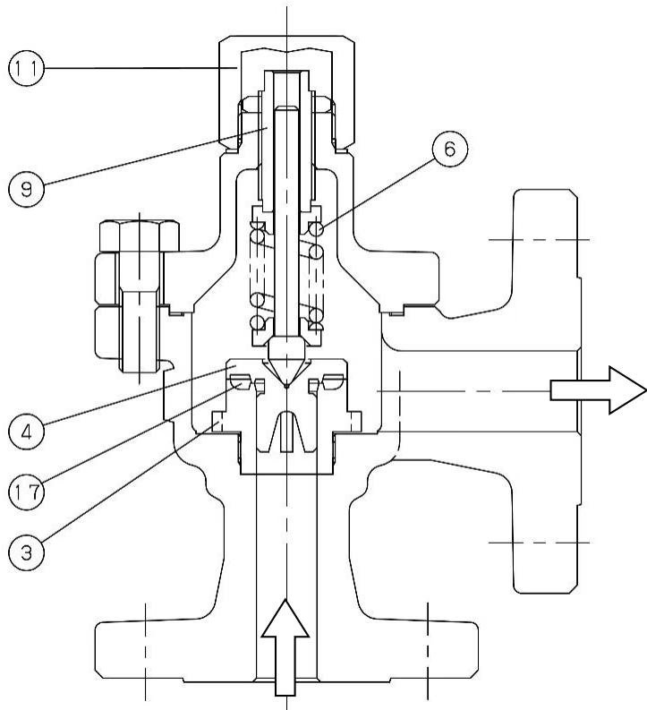
As the inlet pressure approaches the blowout pressure, the force of fluid pushing up the valve approaches the force of the spring pressing down the valve. The safety relief valve commences to blow when the inlet pressure reaches around 3% below the blowout pressure. The fluid accumulates gradually on the pressure groove and when the fluid pressure reaches the blowout pressure the valve pops.
Since the inlet pressure of the safety relief valve decreases when the fluid is released into the atmosphere by the pop action of the valve, the force of fluid lift is lowered. At this point, the repelling force of the spring becomes larger than the force of fluid lift and thus the valve closes. In addition, while the safety relief valve discharges, pressure of fluid entering into the back of the valve (back pressure) adds to the closing force.
WARNING
TIP
WARNING
Daily: Check for corrosion or crack on the product, leakage from the product under normal working pressure, and leakage from joints between the product and piping.
Monthly: Check that there is no loose piping at the inlet and outlet side of the product, and the cap is fastened securely. Check the operation of the product by raising fluid pressure to the set pressure.
Yoshitake Safety Valves / Relief Valves
AF and AL series safety and relief valves for overpressure protection of steam, water, and air equipment.
Explore similar products in our catalog