Lift Type

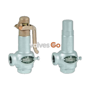
Yoshitake AL-250 and AL-250R closed-type stainless steel relief valves. Features a dash-pot structure to prevent chattering, suitable for water, oil, and non-dangerous fluids up to 1.0 MPa.
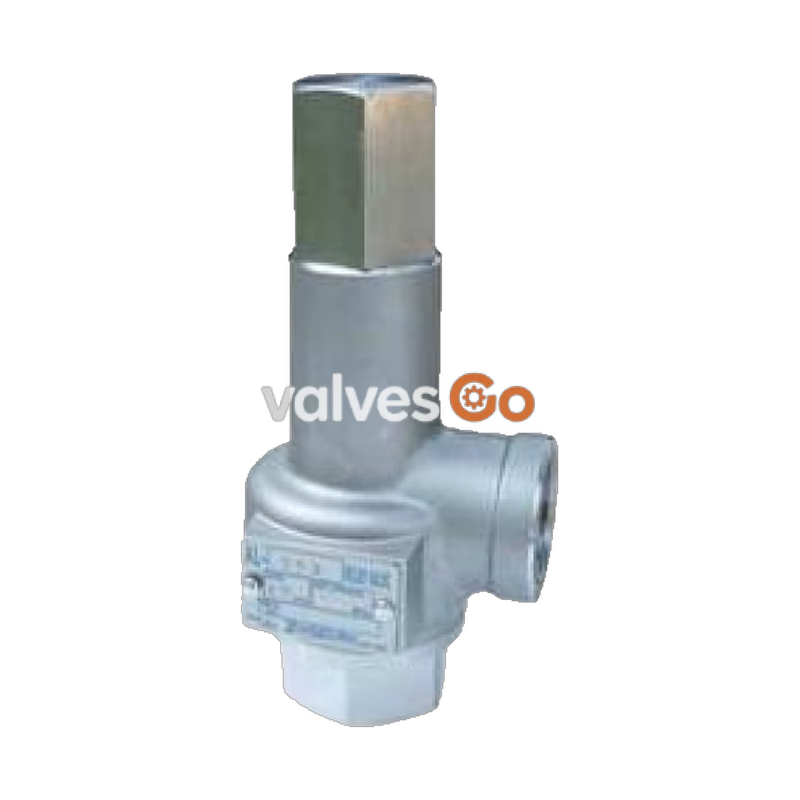
Yoshitake AL-250 and AL-250R are closed-type relief valves designed for regulating pulsating and fluctuating pressures, particularly in large-capacity pump applications. Constructed entirely from stainless steel, these valves offer exceptional corrosion resistance and durability. The unique dash-pot valve structure effectively prevents chattering and hunting, ensuring stable operation even against back pressure changes during continuous blow.
INFO
The operation and maintenance procedures described below also apply to the related AL-260 and AL-260R bronze-body relief valves, which share the same manual.
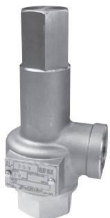 AL-250
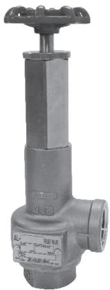 AL-250R
| Model | AL-250 | AL-250R |
|---|---|---|
| Structure | Closed type | Closed type with a handle |
| Application | Cold and hot water, Oil, Other non-dangerous fluids (Less than 20 cSt) | Cold and hot water, Oil, Other non-dangerous fluids (Less than 20 cSt) |
| Working pressure | 0.05 - 1.0 MPa | 0.05 - 1.0 MPa |
| Maximum temperature | 120°C | 90°C |
| Material (Spring case) | Cast stainless steel | Cast stainless steel |
| Material (Valve, valve seat) | Stainless steel | Stainless steel |
| Connection | JIS Rc screwed | JIS Rc screwed |
WARNING
Do not apply the product to devices which do not allow any valve seat leakage. The product has allowable valve seat leakage and does not close completely.
| Nominal size | d | L (mm) | H1 (mm) | H (mm) | Weight (kg) |
|---|---|---|---|---|---|
| 15A | Rc 1/2 | 34 | 41.0 | 129 (185) | 0.7 (0.9) |
| 20A | Rc 3/4 | 38 | 45.0 | 132 (188) | 0.9 (1.1) |
| 25A | Rc 1 | 43 | 51.5 | 148 (203) | 1.2 (1.4) |
| 32A | Rc 1-1/4 | 50 | 63.5 | 184 (241) | 2.2 (2.5) |
| 40A | Rc 1-1/2 | 60 | 68.5 | 210 (278) | 3.2 (3.7) |
| 50A | Rc 2 | 75 | 80.0 | 250 (314) | 5.6 (6.0) |
Note: The values in parentheses are the dimensions and weights of the AL-250R.
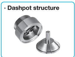 Dashpot structure
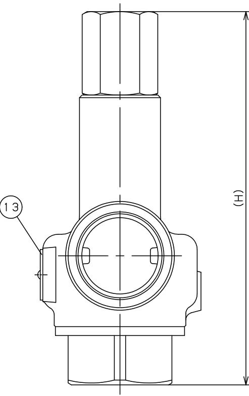
| No. | Name of Parts | Material |
|---|---|---|
| 1 | Spring Case | Cast Stainless Steel (SCS14A or SCS13) |
| 2 | Valve Seat | Stainless Steel (SUS304) |
| 3 | Valve | Stainless Steel (SUS304) |
| 4 | Spindle | Stainless Steel (SUS303) |
| 5 | Spring | Stainless Steel (SUS304) |
| 6 | Bottom Spring Plate | Stainless Steel (SUS304 or SUS303) |
| 7 | Top Spring Plate | Stainless Steel (SUS304 or SUS303) |
| 8 | Adjusting Screw | Stainless Steel (SUS303) |
| 9 | Lock Nut | Stainless Steel (SUS303) |
| 10 | Cap | Stainless Steel (SUS303) |
| 11 | Gasket | PTFE |
| 12 | Gasket | PTFE |
| 13 | Name Plate | Stainless Steel (SUS304) |
The blowout capacity for main pressure is shown in the following table (Accumulation: 25%).
| Nominal size | 0.05 MPa | 0.1 MPa | 0.2 MPa | 0.3 MPa | 0.4 MPa | 0.5 MPa | 0.6 MPa | 0.7 MPa | 0.8 MPa | 0.9 MPa | 1.0 MPa |
|---|---|---|---|---|---|---|---|---|---|---|---|
| 15A | 0.14 | 0.20 | 0.29 | 0.35 | 0.41 | 0.46 | 0.50 | 0.54 | 0.58 | 0.62 | 0.65 |
| 20A | 0.20 | 0.29 | 0.41 | 0.51 | 0.59 | 0.66 | 0.72 | 0.78 | 0.83 | 0.88 | 0.93 |
| 25A | 0.49 | 0.69 | 0.98 | 1.20 | 1.38 | 1.54 | 1.69 | 1.83 | 1.96 | 2.07 | 2.19 |
| 32A | 1.14 | 1.62 | 2.29 | 2.81 | 3.24 | 3.63 | 3.97 | 4.29 | 4.59 | 4.87 | 5.13 |
| 40A | 1.79 | 2.53 | 3.58 | 4.39 | 5.07 | 5.67 | 6.21 | 6.71 | 7.17 | 7.61 | 8.02 |
| 50A | 2.80 | 3.96 | 5.60 | 6.86 | 7.92 | 8.86 | 9.71 | 10.49 | 11.21 | 11.89 | 12.53 |
(Unit: m³/h)
WARNING
TIP
| Trouble | Cause | Remedy |
|---|---|---|
| Blows at a pressure lower than the set pressure. | Foreign substance or scale stuck on contact surface between the valve and valve seat. | Operate the product and eliminate the foreign substance and scale. |
| Damage on the contact surface of valve and valve seat. | The product needs to be disassembled and its parts replaced. | |
| Does not operate at the set pressure. | Sliding parts of the valve and valve seat do not move smoothly. | The product needs to be disassembled and cleaned. |
| There is a back pressure at the piping of the product outlet. | Remove the back pressure. Change the piping layout. | |
| Does not stop blowing. | The normal working pressure exceeds the closing pressure. | Increase the difference between the set pressure and normal working pressure. |
| Leakage from between the cap and the O ring (AL-250R). | Damage on the O ring. | The product needs to be disassembled and its parts replaced. |
WARNING
To adjust the set pressure, turn the adjusting screw (or handle for AL-250R) slowly at the rotation of 1/4-1/3 and confirm the operation each time. Be careful of sudden blowout when turned too much.
For AL-250:
For AL-250R (Handle Type):
Yoshitake Safety Valves / Relief Valves
AF and AL series safety and relief valves for overpressure protection of steam, water, and air equipment.
Explore similar products in our catalog