Lift Type

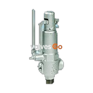
Yoshitake AL-260R Relief Valve. Closed type with handle, featuring a dash-pot structure. Suitable for water, oil, and non-dangerous fluids up to 1.0 MPa and 90°C.
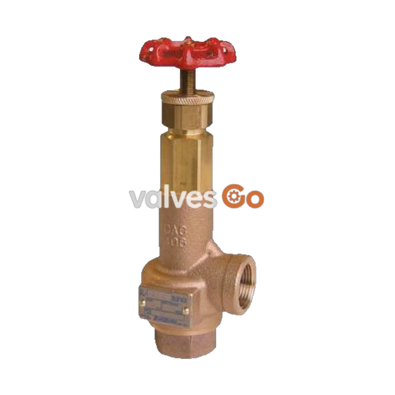
Yoshitake AL-260R is a closed type relief valve with a handle, designed for regulating pulsating and fluctuating pressures for large capacity pumps. It is highly effective for lines with heavy pulsation, preventing chattering and hunting while maintaining stable operation against back pressure changes. The valve features a dash-pot structure and uses stainless steel for trim parts, with a bronze spring case.
| Feature | Specification |
|---|---|
| Structure | Closed type with a handle |
| Application | Cold and hot water, Oil, Other non-dangerous fluids (Less than 20 cSt) |
| Working Pressure | 0.05 - 1.0 MPa |
| Maximum Temperature | 90°C |
| Spring Case Material | Cast bronze |
| Valve, Valve Seat Material | Stainless steel |
| Connection | JIS Rc screwed |
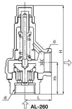
| Nominal Size | d | L (mm) | H1 (mm) | H (mm) | Weight (kg) |
|---|---|---|---|---|---|
| 15A | Rc 1/2 | 34 | 41.0 | 185 | 1.0 |
| 20A | Rc 3/4 | 38 | 45.0 | 190 | 1.2 |
| 25A | Rc 1 | 43 | 51.5 | 200 | 1.5 |
| 32A | Rc 1-1/4 | 50 | 63.5 | 245 | 2.2 |
| 40A | Rc 1-1/2 | 60 | 68.5 | 280 | 3.2 |
| 50A | Rc 2 | 75 | 80.0 | 315 | 5.3 |
The following table outlines the blow-out capacity for the main pressure with an accumulation of 25%.
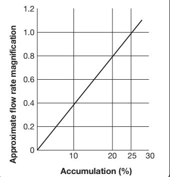
| Nominal Size | 0.05 MPa | 0.1 MPa | 0.2 MPa | 0.3 MPa | 0.4 MPa | 0.5 MPa | 0.6 MPa | 0.7 MPa | 0.8 MPa | 0.9 MPa | 1.0 MPa |
|---|---|---|---|---|---|---|---|---|---|---|---|
| 15A | 0.14 | 0.20 | 0.29 | 0.35 | 0.41 | 0.46 | 0.50 | 0.54 | 0.58 | 0.62 | 0.65 |
| 20A | 0.20 | 0.29 | 0.41 | 0.51 | 0.59 | 0.66 | 0.72 | 0.78 | 0.83 | 0.88 | 0.93 |
| 25A | 0.49 | 0.69 | 0.98 | 1.20 | 1.38 | 1.54 | 1.69 | 1.83 | 1.96 | 2.07 | 2.19 |
| 32A | 1.14 | 1.62 | 2.29 | 2.81 | 3.24 | 3.63 | 3.97 | 4.29 | 4.59 | 4.87 | 5.13 |
| 40A | 1.79 | 2.53 | 3.58 | 4.39 | 5.07 | 5.67 | 6.21 | 6.71 | 7.17 | 7.61 | 8.02 |
| 50A | 2.80 | 3.96 | 5.60 | 6.86 | 7.92 | 8.86 | 9.71 | 10.49 | 11.21 | 11.89 | 12.53 |
| (Units: m³/h) |
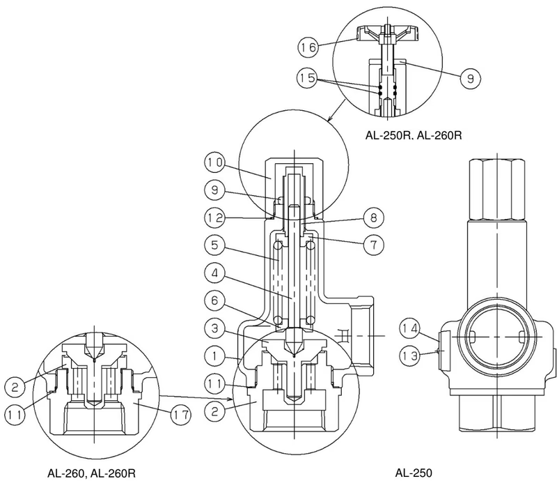
| No. | Part Name | No. | Part Name | No. | Part Name |
|---|---|---|---|---|---|
| 1 | Spring case | 7 | Top spring plate | 13 | Rivet |
| 2 | Valve seat | 8 | Adjusting screw | 14 | Name plate |
| 3 | Valve | 9 | Lock nut | 15 | O ring |
| 4 | Spindle | 10 | Cap | 16 | Handle |
| 5 | Spring | 11 | Gasket | 17 | Valve Case |
| 6 | Bottom spring plate | 12 | Gasket |
Warning
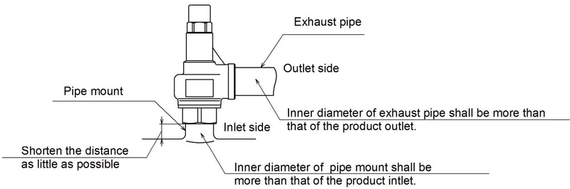
Piping Example
| Trouble | Cause | Remedy |
|---|---|---|
| Blows at a pressure lower than the set pressure | 1. The product specifications are not consistent with the use condition. 2. The pressure gauge is out of order. 3. Foreign substance or scale stuck on contact surface between the valve and valve seat. 4. Damage on the contact surface. 5. The product does not keep the accuracy of its set pressure. | 1. Check the set pressure indication on the name plate and replace with a proper one. 2. Calibrate the pressure gauge or replace it. 3. Eliminate the foreign substance and scale. 4. The product needs to be disassembled and parts replaced. 5. The set pressure needs to be readjusted. |
| Does not operate at the set pressure | 1. The product specifications are not consistent with the use condition. 2. The product does not keep the accuracy of its set pressure. 3. The pressure gauge is out of order. 4. Sliding parts do not move smoothly. 5. There is a back pressure at the piping of the product outlet. | 1. Replace with a proper one. 2. The set pressure needs to be readjusted. 3. Calibrate the pressure gauge or replace it. 4. The product needs to be disassembled and cleaned. 5. Remove the back pressure. |
Set Pressure Range
| Nominal Size | A | B | C | D | E | F |
|---|---|---|---|---|---|---|
| 15A | 0.05~0.2 | 0.21~0.4 | 0.41~0.55 | 0.56~0.75 | 0.76~1.0 | — |
| 20A | 0.05~0.2 | 0.21~0.35 | 0.36~0.45 | 0.46~0.6 | 0.61~0.75 | 0.76~1.0 |
| 25A | 0.05~0.2 | 0.21~0.35 | 0.36~0.45 | 0.46~0.55 | 0.56~0.8 | 0.81~1.0 |
| 32A | 0.05~0.2 | 0.21~0.4 | 0.41~0.65 | 0.66~1.0 | — | — |
| 40A | 0.05~0.2 | 0.21~0.4 | 0.41~0.65 | 0.66~0.8 | 0.81~1.0 | — |
| 50A | 0.05~0.2 | 0.21~0.4 | 0.41~0.65 | 0.66~0.8 | 0.81~1.0 | — |
Yoshitake Safety Valves / Relief Valves
AF and AL series safety and relief valves for overpressure protection of steam, water, and air equipment.
Explore similar products in our catalog