Up to 99.8% Efficiency

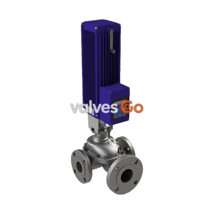
The TLV MC-COS-3 and MC-COS-16 are high-precision motorized multi-control valves for steam, featuring a built-in cyclone separator, free float steam trap, and rapid response actuator.
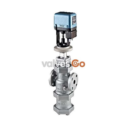
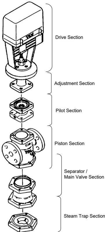
The TLV MC-COS-3 and MC-COS-16 are high-precision multi-control valves for steam that combine a pressure reducing valve, a built-in cyclone separator, a free float steam trap, and a motorized actuator (MC-GA2). When combined with the control algorithms of TLV's SC-F70 or SC-F71 controllers, the rapid response brushless motor precisely adjusts the valve position to ensure extremely accurate pressure control (and temperature control for the MC-COS-16), even during adverse process conditions.
WARNING
The MC-COS-3 cannot be used for temperature control applications. Use the MC-COS-16 for processes requiring temperature control.
| Model | MC-COS-3 | MC-COS-16 |
|---|---|---|
| Connection | Flanged | Flanged |
| Size (DN) | 20 - 50 | 15 - 100 |
| Body Material | Ductile Cast Iron / Cast Iron | Ductile Cast Iron / Cast Iron |
| Max. Operating Pressure (PMO) | 0.3 MPaG | 1.6 MPaG |
| Max. Operating Temperature (TMO) | 220 °C | 220 °C |
| Primary Pressure Range | 0.1 - 0.3 MPaG | 0.2 - 1.6 MPaG |
| Adjustable Pressure Range | 0.01 - 0.05 MPaG | 10 - 84% of primary pressure (min 0.03 MPaG) |
| Minimum Adjustable Flow Rate | 5% of rated flow rate | 5% of rated flow rate (10% for DN 65-100) |
| Parameter | Specification |
|---|---|
| Power Source Voltage | Free between 100 and 240 V AC (50/60 Hz) |
| Power Consumption | Max. 75 VA (with motor running) |
| Operation Input (Valve Opening) | 4 to 20 mA DC (input impedance: approx. 250 Ω) |
| Drive System | Positional control by DC brushless motor |
| Time Required to Fully Open/Close | Approx. 15 seconds |
| Emergency Action | Valve fully closed by an operation signal interruption. When input power is cut off: held at position just before power was cut off. |
| Allowable Ambient Temperature | 0 to 50 °C (32 to 122 °F) |
| Water Resistance | Rain resistant (equivalent to IP54) |
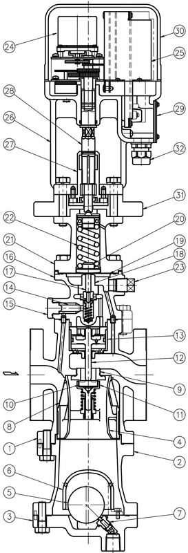
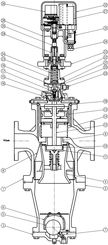
DANGER
Use hoisting equipment for heavy objects (weighing approximately 20 kg or more). Failure to do so may result in back strain or other injury if the object should fall.
TIP
Before installing the MC-COS, be sure to blow down all piping thoroughly. If this is not possible, perform a blowdown using the bypass valve. Blowdown is especially important for newly installed piping or after the system has been shut down for a long period of time.
In order to ensure stable steam flow, the piping upstream and downstream of the MC-COS must be straight runs. If a MC-COS is installed either directly before or after an elbow or control valve, unevenness in steam flow may result in chattering and unstable pressure.
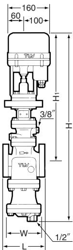
WARNING
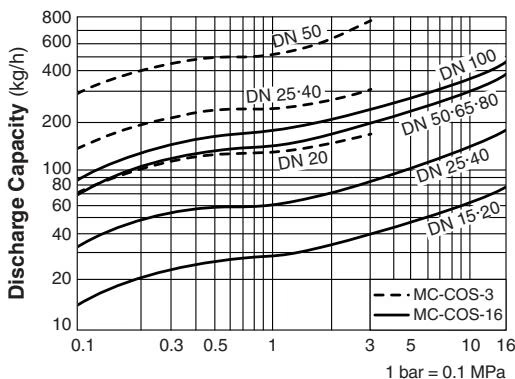
The discharge capacity is the maximum continuous condensate discharge 6 °C below saturated steam temperature. DO NOT use this product under conditions that exceed maximum differential pressure, as condensate backup will occur.
It is a recommended practice to dismantle and inspect the MC-COS once a year for preventive maintenance purposes.
Explore similar products in our catalog