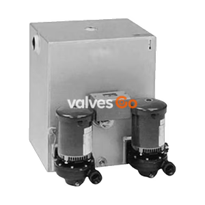
3450 RPM Motors

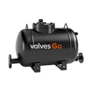
TLV GT14L PowerTrap is a compact mechanical pump with a built-in steam trap for condensate removal and recovery. Handles high-temperature condensate without cavitation.
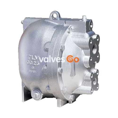
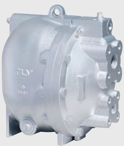
TLV GT14L PowerTrap is a compact mechanical pump with a built-in steam trap designed for a wide range of applications, including the drainage of medium capacity heat exchangers, flash steam recovery systems, and reservoirs often operating under vacuum conditions. The GT model features an integrated steam trap function, making it suitable for use in instances where the inlet pressure may alternately be lower than or higher than the outlet pressure.
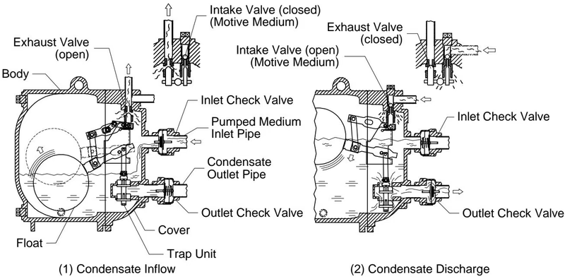
It handles high-temperature condensate without cavitation and requires no electric power or additional level controls, making it intrinsically safe. The pump operates with a low filling head (minimum 300 mm) and features an inline design for easy access to internal parts, simplifying cleaning and reducing maintenance costs. High-quality stainless steel internals and hardened working surfaces ensure long-term reliability.
WARNING
Install properly and DO NOT use this product outside the recommended operating pressure, temperature, and other specification ranges. Improper use may result in hazards such as damage to the product or malfunctions which may lead to serious accidents.
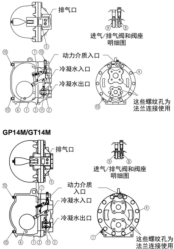
| No. | Part Name | Material | DIN | ASTM/AISI |
|---|---|---|---|---|
| 1 | Body | Cast Iron FC250 / Cast Steel A216 Gr.WCB | 0.6025 / 1.0619 | A126 Cl.B / - |
| 2 | Cover | Cast Iron FC250 / Cast Steel A216 Gr.WCB | 0.6025 / 1.0619 | A126 Cl.B / - |
| 3 | Cover Gasket | Graphite Compound | - | - |
| 4 | Float | Stainless Steel SUS316L | 1.4404 | AISI316L |
| 5 | Snap-action Unit | Stainless Steel | - | - |
| 6 | Motive Medium Intake Valve Unit | Stainless Steel SUS440C (Valve) / SUS420F (Seat) | 1.4125 / 1.4028 | AISI440C / AISI420F |
| 7 | Exhaust Valve Unit | Stainless Steel SUS440C (Valve) / SUS420F (Seat) | 1.4125 / 1.4028 | AISI440C / AISI420F |
| 8 | Steam Trap Unit | Stainless Steel | - | - |
| 9 | Inlet Check Valve CKF5M | Stainless Steel SUS304 | 1.4301 | AISI304 |
| 10 | Outlet Check Valve CKF3M | Cast Stainless Steel A351 Gr.CF8 | 1.4312 | - |
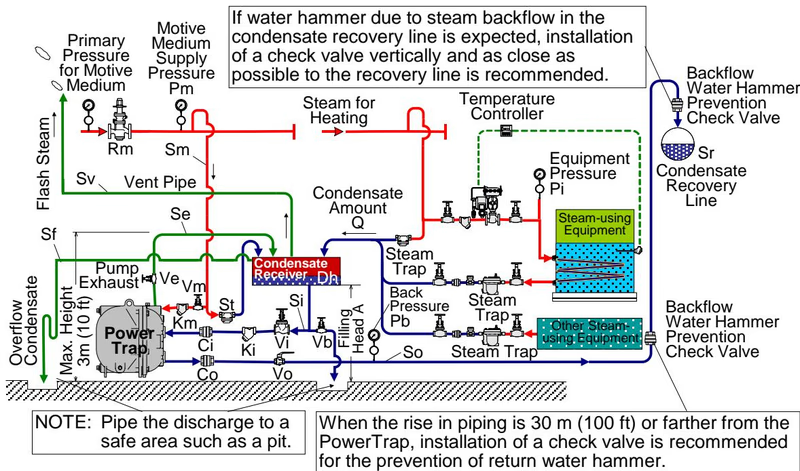
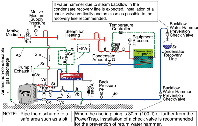
There are two types of delivery systems (piping methods): the closed system and the open system. Use of the GT model or the GP model is determined by the type of system.
INFO
For Open Systems: Steam, compressed air, or nitrogen may be used as the motive medium. An overflow pipe should be installed at the side of the receiver to discharge condensate to a safe area if venting flash steam to a high area.
INFO
For Closed Systems: Use steam as the motive medium. Except in special cases, do not use non-condensable gases such as air or nitrogen. The exhaust pipe must be connected to the top of the reservoir.
Weight:
TIP
A check valve must be installed at both the pumped medium inlet and outlet. To achieve the rated capacities with the standard GT14L configuration, TLV check valves CKF5M for inlet and CKF3M for outlet must be used.
There are two types of periodic inspection: the visual inspection and the disassembly inspection.
Explore similar products in our catalog