Repairable

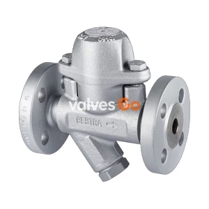
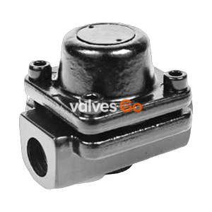
TLV FL21 and FL32 QuickTrap balanced pressure thermostatic steam traps feature a fail-open design, universal two-bolt flange, and inline replaceability.
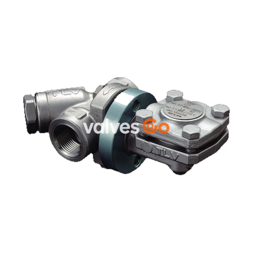
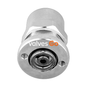
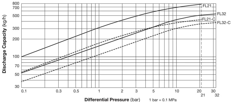
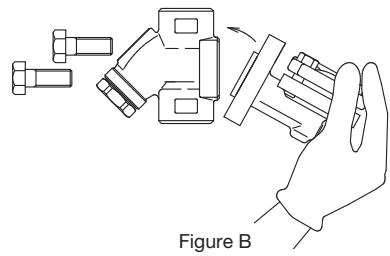
TLV FL21 and FL32 QuickTrap series are universal balanced pressure thermostatic steam traps featuring a "fail open" design. These inline replaceable and cleanable two-bolt universal flange steam traps offer high air venting capability, making them ideal for steam mains, tracers, dryers, and heaters. The universal flange allows the trap to be positioned in the correct attitude regardless of pipeline configuration, and the two-bolt connector permits trap replacement or cleaning in minutes without disturbing the piping.
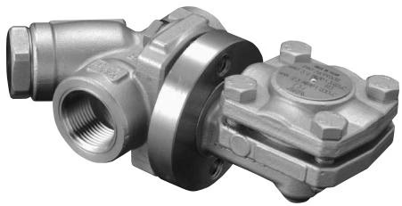
The rugged yet light construction withstands superheat and water hammer. It provides cyclic operation with fixed subcooling (up to 6°C) throughout the whole pressure range. Built-in screens in the connector and trap body protect the internals and keep trap module replacement costs low. The valve head and seat are made of hardened stainless steel for extended service life.
| Model | FL21 | FL32 |
|---|---|---|
| Connection | Screwed, Socket Welded, Flanged | Screwed, Socket Welded, Flanged |
| Size | 1/2", 3/4", 1" / DN 15, 20, 25 | 1/2", 3/4", 1" / DN 15, 20, 25 |
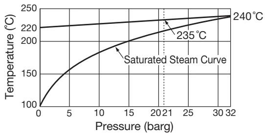
| Max. Operating Pressure (PMO) | 21 barg | 32 barg |
| Min. Operating Pressure | 0.1 barg | 0.1 barg |
| Maximum Back Pressure | 90% of inlet pressure | 90% of inlet pressure |
| Subcooling of X-element Fill | up to 6°C | up to 6°C |
| Type of X-element | C6 | C6 |
| Connector Unit | F46 | F46 |
| Trap Unit | L21 | L32 |
Designed for use with the F46, F32 Connector Units and V1/V2 Trap Stations. Trap and Connector Units are sent as separate units for flexible installation.
WARNING
To avoid malfunctions, product damage, accidents or serious injury, install properly and DO NOT use this product outside the specification range. Local regulations may restrict the use of this product to below the conditions quoted.
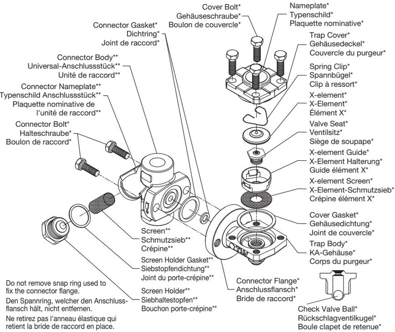
| No. | Description | Material | ASTM/AISI |
|---|---|---|---|
| 1 | Trap Body | Cast Stainless Steel | A351 Gr.CF8 |
| 2 | Connector Body | Cast Stainless Steel | A351 Gr.CF8 |
| 3 | Connecting Flange | Carbon Steel | A105/A105M |
| 4 | Snap Ring | Carbon Steel | AISI 1055 |
| 5 | Outer Connector Gasket | Graphite/Stainless Steel | -/AISI 304 |
| 6 | Inner Connector Gasket | Graphite/Stainless Steel | -/AISI 304 |
| 7 | Valve Seat | Stainless Steel | AISI 420F |
| 8 | Trap Cover | Carbon Steel | A105/A105M |
| 10 | Cover Gasket | Graphite/Stainless Steel | -/AISI 316L |
| 11 | Screen inside/outside | Stainless Steel | AISI 304/430 |
| 13 | X-element | Stainless Steel | - |
| 22 | Steel Ball (Check Valve)* | Stainless Steel | AISI 440C |
*For models FL21-C and FL32-C with built-in check valve.
| Part & Number | Torque N·m (lbf·ft) | Distance Across Flats mm (in) |
|---|---|---|
| Cover Bolt 18 | 35 (26) | 13 (1/2) |
| Valve Seat 7 | 35 (26) | 19 (3/4) |
| Connector Bolt 8 | 39 (28) | 14 (9/16) |
| Screen Holder (F46) 13 | 100 (73) | 30 (1 3/16) |
| Size | L (mm) | W (mm) | W1 (mm) | Weight (kg) |
|---|---|---|---|---|
| 1/2" | 80 | 169 | 105 | 1.8 |
| 3/4" | 80 | 169 | 105 | 1.8 |
| 1" | 96 | 171 | 109 | 2.1 |
| DN | L (mm) | W (mm) | W1 (mm) | φD (mm) | φC (mm) | h (mm) | Weight (kg) |
|---|---|---|---|---|---|---|---|
| 15 | 80 | 169 | 105 | 36 | 21.8 | 12 | 1.8 |
| 20 | 80 | 169 | 105 | 36 | 27.2 | 12 | 1.8 |
| 25 | 96 | 171 | 109 | 44 | 33.9 | 14 | 2.1 |
| DN | L (mm) | W (mm) | W1 (mm) | Weight (kg)* |
|---|---|---|---|---|
| 15 | 150 | 169 | 105 | 3.4 |
| 20 | 150 | 169 | 105 | 4.3 |
| 25 | 160 | 171 | 109 | 4.8 |
*Weight is for DIN PN 25/40. Length and weight may vary for other standards.
TIP
Install the trap in the lowest part of the pipeline or equipment so the condensate flows naturally into the trap by gravity. The inlet pipe should be as short and have as few bends as possible.
Horizontal Piping Example: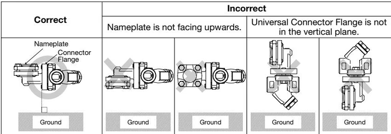
Vertical Piping Example: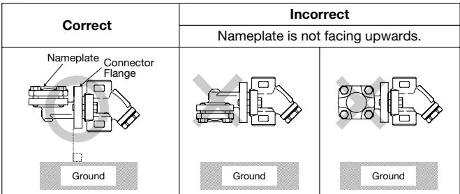
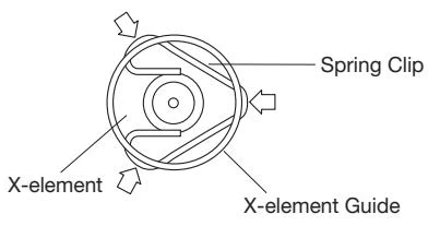
If the expected performance is unachievable after installation, check the following points:
| Problem | Cause | Remedy |
|---|---|---|
| Condensate is not discharged or discharge is poor | X-element is stuck to the valve seat | Clean |
| Screens and/or inlet/outlet channels are clogged | Clean | |
| Steam-locking | Study piping | |
| Trap operating pressure exceeds maximum specified | Study inlet pressure | |
| Differential pressure is insufficient | Study inlet/outlet pressure | |
| Steam leakage or blow-off | Valve closure is obstructed by rust or scale | Clean (inspect screens as well) |
| X-element and/or valve seat are worn or damaged | Replace X-element and/or valve seat | |
| X-element is broken | Replace X-element | |
| Severe vibration of trap | Reinforce trap piping supports | |
| Leakage from another location | Gaskets of connector, trap cover, screen holder or valve seat are worn | Repair gaskets |
| Bolts or valve seat are loose | Tighten to proper torque | |
| Bypass valve is open or damaged | Repair or close valve |
The BD2 Blowdown Valve uses internal pressure to blow out condensate or steam (and scale/dirt) from inside the unit to atmosphere. Always wear eye protection and heat-resistant gloves when operating the blowdown valve. Do not use excessive force when opening the blowdown valve.
Explore similar products in our catalog