Up to 99.8% Efficiency

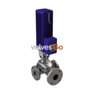
TLV CV-COS-20D electro-pneumatic control valve with built-in cyclone separator and steam trap. Features digital I/P positioner, 21 barg max pressure, and 220°C max temperature for high-quality steam control.
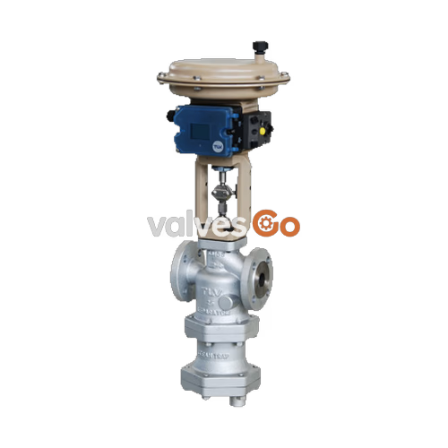
The TLV CV-COS-20D is an electro-pneumatic control valve featuring a digital I/P positioner combined with a compact pneumatic actuator. It includes a built-in cyclone separator and a self-modulating free float steam trap to provide high-quality, dry steam for process applications. By removing condensate while the valve is closed, it reduces scale adhesion and water hammer, improving productivity and product quality.
| Model | CV-COS-20D |
|---|---|
| Body Material | Ductile Cast Iron (EN 5.3103) / Cast Stainless Steel (A351/A351M Gr.CF8M) |
| Connection | Flanged PN25 DIN EN 1092-2 / Flanged PN40 DIN EN 1092-2 |
| Size (DN) | 15, 20, 25, 40, 50, 65, 80, 100 |
| Max. Operating Pressure (PMO) | Up to 21 barg (depends on size and material) |
| Max. Operating Temperature (TMO) | 220 °C |
| Leak Rate Class (IEC 60534-4) | Class IV / Metal sealing |
| Characteristic | Equal percentage or linear |
| Rangeability | 50 : 1 |
| Applicable Fluid | Steam |
WARNING
Do not use with toxic, flammable or otherwise hazardous fluids.
| Parameter | Value |
|---|---|
| Fail-safe Position | Valve CLOSED (Air to Open) |
| Motive Medium | Oil-free air, filtered to 5 μm |
| Electrical Input Signal (mA) | 4 to 20 |
| Load Impedance (V) | Max. 6.3 |
| Air Supply Pressure Range for Positioner (barg) | 4.4 to 6 |
| Ambient Temperature Range (°C) | -20 to +80 |
| Protection Class | IP 66 |
| Intrinsically Safe Rating (optional) | ATEX II 2G Ex ia IIC T4 |
| DN | Actuator Area (cm²) | Spring Bench Range (bar) | Min. Air Supply Pressure (barg) | Max. Differential Pressure (bar) |
|---|---|---|---|---|
| 15, 20, 25 | 175 | 0.8 to 2.4 | 2.6 | 21 |
| 40, 50 | 355 | 1.6 to 2.4 | 2.6 | 21 |
| 65 | 355 | 2.4 to 3.6 | 3.8 | 21 |
| 80 | 750 | 1.6 to 2.4 | 2.6 | 20 |
| 100 | 750 | 2.5 to 4.2 | 4.4 | 20.5 |
Subject to limitation of maximum operating pressure rating of valve (PMO).
| Stroke (mm) | Kvs (DIN) | Cv (UK) | Cv (US) | DN \ Seat Dia. (mm) | 12 | 24 | 38 | 48 | 63 | 80 | 100 |
|---|---|---|---|---|---|---|---|---|---|---|---|
| 15 | 4 | 3.9 | 5 | 15 | ○ | ||||||
| 15 | 6.3 | 6.1 | 7.5 | 20 | ○ | ||||||
| 15 | 10 | 9.7 | 12 | 25 | ○ | ||||||
| 15 | 25 | 24.3 | 30 | 40 | ○ | ||||||
| 15 | 40 | 38.8 | 47 | 50 | ○ | ||||||
| 15 | 60 | 58.2 | 70 | 65 | ○ | ||||||
| 15 | 80 | 77.6 | 95 | 80 | ○ | ||||||
| 30 | 160 | 155 | 190 | 100 |
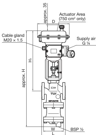
| DN | L (PN25) | L (PN40) | Actuator Area (cm²) | H | H1 | W | ΦD | Weight (kg) |
|---|---|---|---|---|---|---|---|---|
| 15 | 130 | 130 | 175 | 605 | 401 | 105 | 215 | 22 |
| 20 | 150 | 150 | 175 | 605 | 401 | 105 | 215 | 22 |
| 25 | 160 | 160 | 175 | 645 | 401 | 150 | 215 | 24 |
| 40 | 200 | 200 | 355 | 725 | 445 | 165 | 280 | 38 |
| 50 | 230 | 230 | 355 | 780 | 445 | 195 | 280 | 51 |
| 65 | 290 | 290 | 355 | 820 | 484 | 195 | 280 | 97 |
| 80 | 310 | 310 | 750 | 970 | 502 | 394 | 394 | 121 |
| 100 | 350 | 350 | 750 | 1165 | 594 | 394 | 394 | 245 |
Weight is for DIN PN 25 in ductile cast iron.
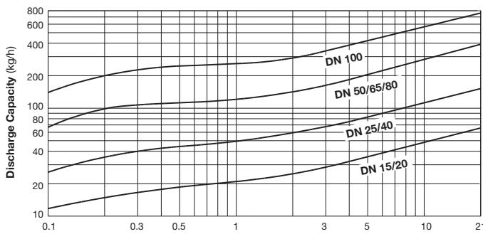
DANGER
DO NOT use this product under conditions that exceed maximum differential pressure, as condensate backup will occur!
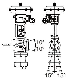
Install the product vertically, so that the arrow mark on the body points horizontally in the direction of flow. Allowable inclination is 10 degrees in the fore-aft direction and 15 degrees in the plane perpendicular to the flow line.
Leave sufficient space for maintenance, inspection and repair.

Install the product, paying attention to avoid excessive load, bending and vibration. Support the inlet and outlet pipes securely.
Connect the outlet pipe to a condensate return line, or extend it to a trench. In the case of the latter, make sure the end of the pipe is above the waterline. (Dirt and water may be sucked up by the vacuum formed during trap closure and system shutdown.)
Supply to the actuator only clean air that does not contain water, oil or foreign matter. To prevent malfunction due to contamination of the air supply, installation of the optional air filter regulator (5 µ filter) and mist separator (0.3 µ filter) as a set is recommended.
A visual inspection of the following items should be done on a daily basis to determine whether the product is operating properly or has failed.
| Inspection Item | Inspection Method | Remedy |
|---|---|---|
| Leakage from valve (when valve is closed) | Visual Inspection or Stethoscope Inspection: Is the outlet side pressure or temperature elevated, or is there the sound of the medium flowing? | Adjust the zero/span; if that does not solve the problem, replace with a new valve plug & stem and valve seat |
| Leakage from gland area | Visual Inspection: Is liquid leaking from the slit between the gland and the valve stem? | Coat the gland and the valve stem thoroughly with grease; thoroughly grease the V-ring slot; or replace with a new V-ring |
| Leakage from the gaskets | Visual inspection: Is fluid leaking from the gasket areas on pressurized parts? | Apply additional tightening (refer to recommended torque) or replace with new gaskets |
| Leakage from pressure-bearing parts | Visual Inspection: Is fluid leaking from the body or bonnet? | Replace any pressurized parts at leak locations |
| Leakage from the trap area | Visual inspection or stethoscope inspection: Is live steam being discharged from the trap outlet piping, or can the sound of a steam leak be heard? | Clean the sealing surface of the trap valve seat or replace the valve seat |
| Problem | Cause | Remedy |
|---|---|---|
| Valve Leakage | The pressure of the air supply to the actuator or positioner is too high | Adjust the pressure of the air supply for the positioner to match the product specifications |
| The positioner's zero point is miscalibrated | Adjust the positioner's zero point | |
| The inlet pressure for the product is too high | Decrease the inlet pressure to the maximum operating pressure (PMO) or less | |
| The valve plug and valve seat are off-center | Reassemble the valve bonnet section correctly | |
| There is a problem with the sealing surfaces | Replace with a new valve plug & stem and valve seat |
| Problem | Cause | Remedy |
|---|---|---|
| Steam is blowing | Build-up of dirt on the trap valve seat or on the float | Clean or replace with a new trap valve seat or float |
| The body is installed tilted | Correct the installation | |
| The float is deformed | Replace with a new float | |
| There is vibration in the piping | Remove the source of the vibration or reinforce the piping supports | |
| No condensate is discharged | Primary pressure exceeds the trap valve seat maximum working pressure | Decrease the inlet pressure to the maximum operating pressure (PMO) or less |
| Water is inside the float | Replace with a new float | |
| Output piping is clogged | Clean or modify the piping | |
| The trap valve seat is clogged | Clean or replace with a new trap valve seat |
Explore similar products in our catalog