PN25
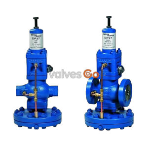
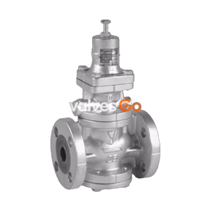
Spirax Sarco 25P Series Pilot Operated Pressure Reducing Valve, sizes ½" - 5", features self-acting design with external pressure sensing line to maintain stable downstream pressure. Body material options include ductile iron or cast steel, with stellite-faced plug for tight shut-off under no-load conditions. Ideal for steam systems requiring high-to-low pressure reduction, providing precise pressure control within equipment operating range to prevent damage. A reliable pressure control solution for industrial steam systems.
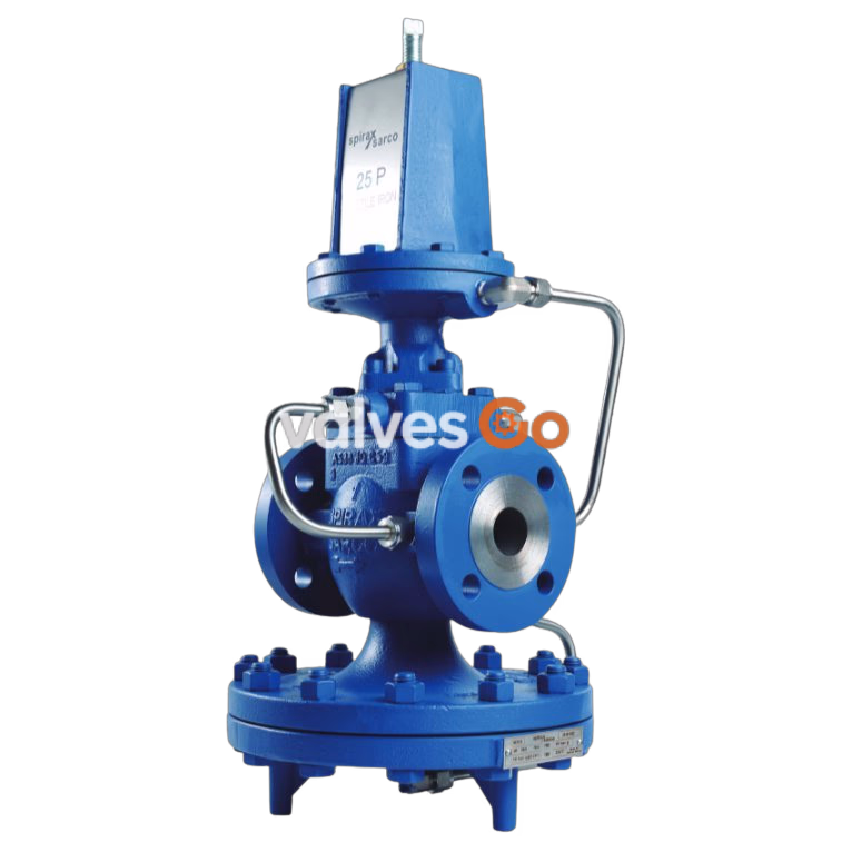
Spirax Sarco 25P Series self-acting pilot operated pressure reducing valve, sizes ½" to 5", is specifically designed for steam systems. The product senses downstream pressure in real-time through an external pressure sensing line, automatically adjusting main valve opening to ensure downstream pressure remains stable within the set range. The main valve features a single-seat design with stellite-faced plug, providing excellent sealing and durability. The valve body is available in ductile iron or cast steel, with the pilot valve bolted directly to the main valve for compact structure and easy installation. Under no-load downstream conditions, the valve can close completely, preventing media waste and system pressure fluctuations. It effectively reduces high-pressure steam to the required working pressure for equipment, protecting equipment from high-pressure damage.
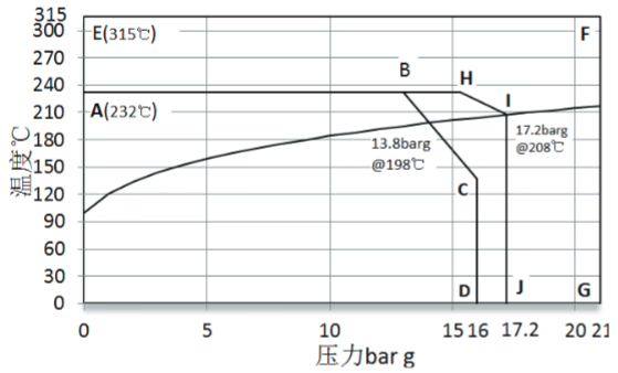
| Material Type | Flange Standard | Max Operating Pressure (bar g) | Max Operating Temperature (℃) |
|---|---|---|---|
| Ductile Iron (A-B-C-D) | PN16 | 16 | 232 |
| Ductile Iron (A-H-I-J) | PN25 | 25 | 270 |
| Cast Steel (E-F-G) | PN40 | 40 | 270 |
| Spring Color | Pressure Range (bar g) |
|---|---|
| Yellow | 0.2 - 2.1 |
| Blue | 1.4 - 7.0 |
| Red | 5.6 - 14.0 |
| Size Range | Connection Type | Applicable Flange Standards |
|---|---|---|
| ½" - 2" | Threaded BSPT(BS21), Flanged | PN16, PN25 (Ductile Iron) |
| ½" - 4" | Flanged | PN16, PN25 (Ductile Iron), PN40 (Cast Steel) |
| 5" | Flanged | PN16, PN25 (Ductile Iron) |
| Size | ½" | ¾" | 1" | 1¼" | 1½" | 2" | 2½" | 3" | 4" | 5" |
|---|---|---|---|---|---|---|---|---|---|---|
| Cv Value | 3.48 | 6.5 | 10.5 | 14 | 20 | 35 | 56 | 74 | 115 | 123 |
Note
Conversion formula: Cv(US) = Kv × 1.156
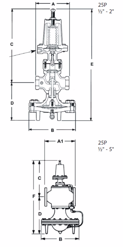
| Size | A | B | C | D | E |
|---|---|---|---|---|---|
| ½" | 140 | 193 | 309 | 157 | 466 |
| ¾" | 140 | 193 | 309 | 157 | 466 |
| 1" | 152 | 219 | 308 | 171 | 479 |
| 1¼" | 184 | 219 | 322 | 179 | 501 |
| 1½" | 184 | 219 | 322 | 179 | 501 |
| 2" | 216 | 269 | 338 | 208 | 546 |
| 2½" | - | 346 | 297 | 354 | 651 |
| 3" | - | 346 | 294 | 367 | 661 |
| 4" | - | 397 | 325 | 410 | 735 |
| 5" | - | 397 | 325 | 410 | 735 |
| Size | Ductile Iron BSP JIS/KS10 | Ductile Iron PN16 | Ductile Iron PN25/PN40 | Cast Steel |
|---|---|---|---|---|
| ½" | - | 160 | 160 | 150 |
| ¾" | - | 160 | 160 | 154 |
| 1" | - | 166 | 166 | 160 |
| 1¼" | - | 205 | 205 | - |
| 1½" | - | 216 | 216 | 200 |
| 2" | - | 240 | 240 | 230 |
| 2½" | 286 | 284 | 288 | 292 |
| 3" | 308 | 308 | 316 | 317 |
| 4" | 354 | 353 | 361 | 368 |
| 5" | - | 400 | 400 | - |
| Size | Threaded | Flanged |
|---|---|---|
| ½" | 10.8 | 11.4 |
| ¾" | 10.2 | 12.2 |
| 1" | 13.6 | 16.0 |
| 1¼" | 16.0 | 18.8 |
| 1½" | 15.8 | 20.4 |
| 2" | 26.0 | 31.2 |
| 2½" | - | 62.4 |
| 3" | - | 74.6 |
| 4" | - | 112.2 |
| 5" | - | 132.0 |
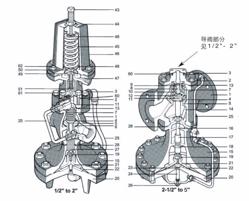
| No. | Component | Material | Standard/Grade |
|---|---|---|---|
| 1 | Body | Ductile Iron | QT400-18 |
| 2 | Cover | Ductile Iron | QT400-18 |
| 3 | Cover Bolt | Steel | SAE J 429 Grs |
| 4 | Main Plug | Stainless Steel | AISI 420 |
| 5 | Main Seat | Stainless Steel (½"-2") | AISI 420 |
| 5 | Main Seat | Stainless Steel (2½"-5") | AISI 304 |
| 6 | Main Seat Gasket | Copper | - |
| 7 | Valve Return Spring | Stainless Steel | AISI 302 |
| 8 | Stem | Stainless Steel | AISI 304 |
| 9 | Strainer | Stainless Steel | AISI 304 |
| 10 | Stem Sleeve | Stainless Steel (2½"-5") | AISI 420 |
| 10 | Stem Sleeve | Brass (½"-2") | ASTM B 283 |
| 11 | Spring Guide | Steel (2½"-5") | - |
| 12 | Nut | Steel | SAE J 995 |
| 13 | Cover Gasket | Non-asbestos | - |
| 14 | Pressure Balance Tube | Stainless Steel | AISI 304 |
| 15 | Diaphragm Top Cover | Ductile Iron | QT400-18 |
| 16 | Stem Bushing | Stainless Steel | AISI 304 |
| 17 | Diaphragm Disc Pushrod | Stainless Steel | AISI 304 |
| 18 | Pushrod Guide | Stainless Steel (2½"-5") | AISI 304 |
| 18 | Pushrod Guide | Brass (½"-2") | - |
| 19 | Nut | Steel (2½"-5") | SAE J 995 |
| 20 | Diaphragm Bottom Cover | Ductile Iron | QT400-18 |
| 21 | Diaphragm Disc | Brass (½"-2") | ASTM B 283 |
| 21 | Diaphragm Disc | Ductile Iron (2½"-5") | QT400-18 |
| 22 | Main Diaphragm (2 ply) | Phosphor Bronze (½"-3") | - |
| 22 | Main Diaphragm (2 ply) | Stainless Steel (4"-5") | - |
| 23 | Sleeve | Stainless Steel | 12L14 |
| 24 | Nipple and Orifice | Stainless Steel | AISI 304 |
| 25 | External Tubing Assembly | Stainless Steel | ASTM B 280 |
| 26 | Plug | Steel | SAE 12 L 14 |
| 27 | Connection Bolt | Stainless Steel | AISI 304 |
| 28 | Gasket | Copper (½"-2") | Non-asbestos |
| 28 | Gasket | Graphite (2½"-5") | - |
| 43 | Adjusting Screw | Steel | - |
| 44 | Lock Nut | Brass | - |
| 45 | Pilot Spring | Steel | SAE 1060 |
| 46 | Diaphragm Top Cover | Ductile Iron | QT400-18 |
| 47 | Diaphragm Bottom Cover | Ductile Iron | QT400-18 |
| 48 | Spring Plate | Steel | SAE 1010 |
| 49 | Diaphragm | Phosphor Bronze | - |
| 50 | Diaphragm Plate | Brass | ASTM B 283 |
| 51 | Pilot Spring | Stainless Steel | AISI 302 |
| 60 | Pilot Gasket | Graphite/Asbestos | AISI 302 |
| 61 | Pilot Mounting Nut | Steel | SAE J 429 Grs |
| 62 | Diaphragm Chamber Nut | Steel | SAE J 429 Grs (Spec: 5/16"-18×1") |
Installation Requirements
Caution
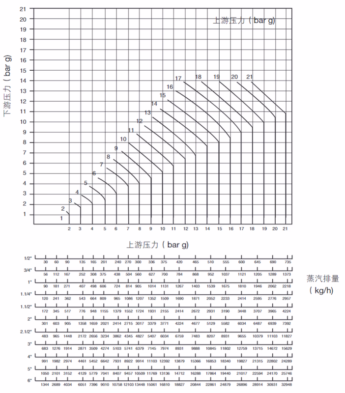
Flow calculations are based on external sensing line installation. Without external sensing line, flow will be reduced; at very low downstream pressures, flow reduction can reach up to 30%.
Selection Guidelines
The 25P Pilot Operated Pressure Reducing Valve provides precise and reliable performance, primarily used in industrial steam systems for applications requiring high-pressure steam reduction to equipment effective working pressure, including but not limited to:
Explore similar products in our catalog