WirelessHART 2.4 GHz

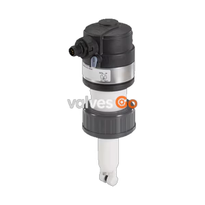
Burkert 574629 (Type 8318) pressure transmitter with IO-Link interface. Features a G 3/4 flush diaphragm, -0.4 to 0.4 bar measuring range, and IP65 protection.
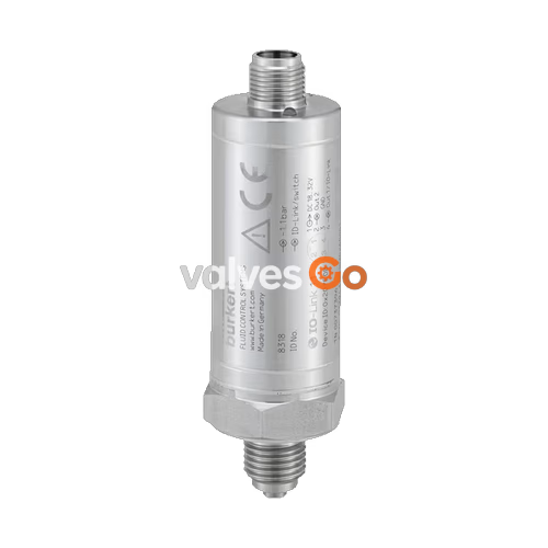
Burkert Type 8318 (Model 574629) pressure transmitter measures and monitors relative pressure in liquids and gases. The effect of the pressure on the sensor element generates a signal which is amplified, digitised, and processed. Instead of an analogue output, this device offers a digital IO-Link interface (specification version 1.1), allowing bidirectional data transfer with any IO-Link master. Data access occurs through the available standardised IO Device Description (IODD).
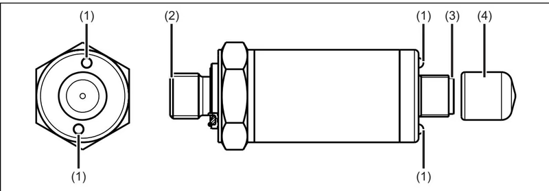
The bidirectional communication is used to read process data, parameters, diagnostic information, and status messages, as well as to set parameters. The two green LEDs are permanently lit as soon as power is supplied to the device. Once an IO-Link connection has been established, the LEDs flash. The switching behaviour and the switching thresholds of the digital outputs (maximum of 2, "PNP" or "NPN") can be individually configured.
Key Features
| Property | Description |
|---|---|
| Housing | Stainless steel 1.4301 (304) |
| Process connection | Stainless steel 1.4404 (316L) |
| Measuring element | Membrane in stainless steel 1.4435 (316L), Welding ring in stainless steel 1.4404 (316L) |
| Measurement technology | Metallic thin film strain gauge |
| Measuring range | -0.4...+0.4 bar |
| Measurement deviation | At 20 °C: 0.7% of measuring span At -20 °C...+80 °C: 2.0% of measuring span |
| Linearity | 0.3% of measuring span |
| Overload limit | 1 bar |
| Burst pressure | 1.5 bar |
| Response time | Digital switching output: ≤7 ms IO-Link: ≤9 ms |
| Property | Description |
|---|---|
| Operating voltage | In IO-Link operation: 18...32 V DC, filtered and regulated In switch operation: 9.6...32 V DC, filtered and regulated |
| Current consumption | In idle operation: ≤ 10 mA In IO-Link operation: ≤ 12 mA In switch operation: ≤ 250 mA (with two digital outputs) |
| Number of outputs | 1 digital output in IO-Link operation 2 digital outputs for switch operation (SIO-mode) |
| Switching function | Hysteresis function (configurable) or window function (fixed setting, symmetrical, ± 0.25% of the measuring range) NC or NO contact Digital output PNP or NPN Switch-on/switch-off delay (0...100 s) |
| Switching current | ≤ 100 mA per output |
| Electrical connection | M12 × 1 male connector, 4 pins, A-coded, non rotating (IO-Link port class A) |
| Property | Description |
|---|---|
| Fluid | Liquid and gaseous medium |
| Fluid temperature | -40...+125 °C (-40...+257 °F) |
| Ambient temperature | Operation and storage: -40...+85 °C (-40...+185 °F) |
| Degree of protection | IP65 according to DIN EN 60529, with female connector screwed on |
With G 3/4 front-flush process connection according to ISO 228-1
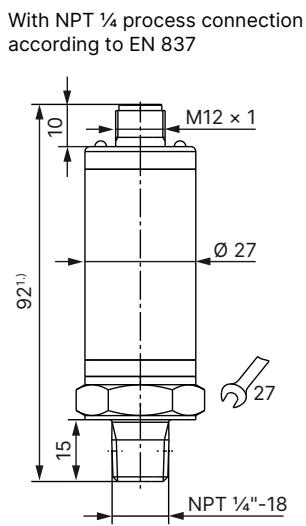
Note: Dimensions in mm. The total height is increased by the height of the used female connector and cable.
M12 × 1 round plug (A-coded, non rotating) Terminal Assignment
| Connection | Pin | Assignment |
|---|---|---|
| Switch operation | ||
| Voltage supply DC 9.6 to 32 V | 1 BN (brown) 3 BU (blue) | L+ L- |
| Switching output 1 | 4 BK (black) | C/Q = OUT1 |
| Switching output 2 | 2 WH (white) | I/Q = OUT2 |
| IO-Link operation | ||
| Voltage supply DC 18 to 32 V | 1 BN (brown) 3 BU (blue) | L+ L- |
| IO-Link | 4 BK (black) | C/Q = IO-Link |
| Switching output 2 | 2 WH (white) | I/Q = OUT2 |
WARNING
The auxiliary energy of the pressure sensor must meet SELV requirements; optionally, an energy-limited current circuit according to DIN EN 61010-1 and UL 61010-1 can be used. The pressure sensor must be connected to the plant's potential equalization system via the process connection.
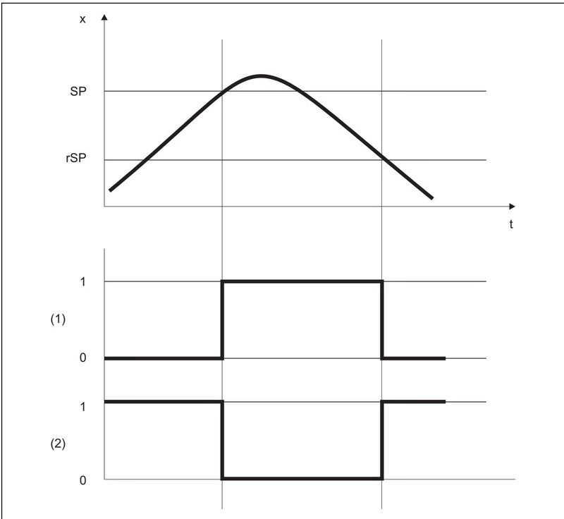
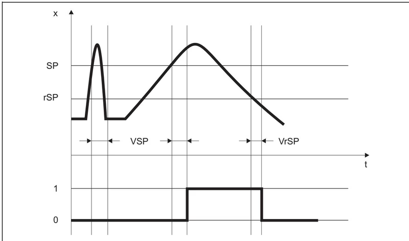
The hysteresis function switches the output as soon as the switching point "SP" is reached. When the release point "rSP" is reached, the output switches again. The hysteresis function distinguishes between N/C and N/O contacts.
Switching requirement: Switching point "SP" ≥ Release point "rSP"
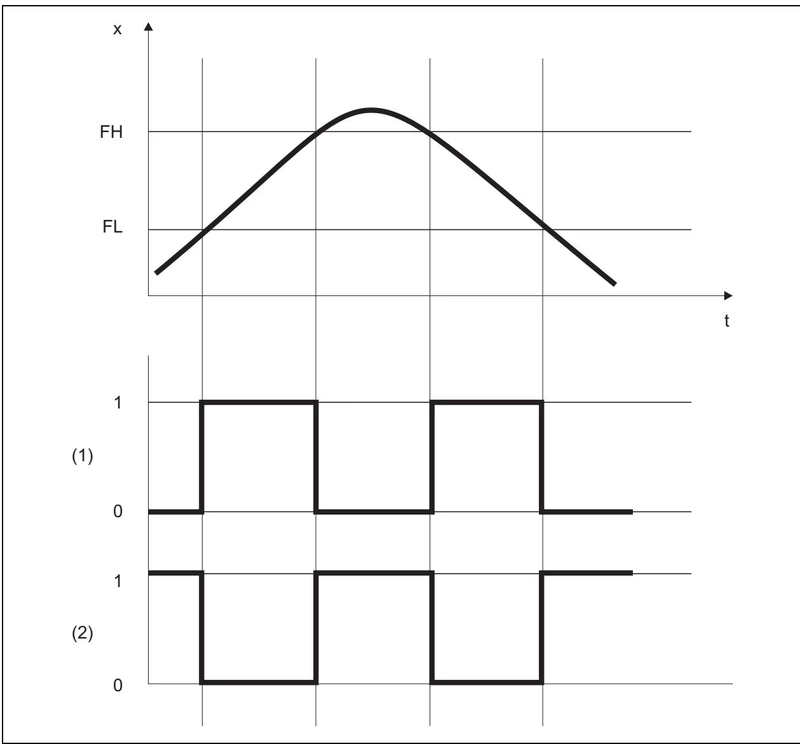
Under the window function, the window range is defined using the parameters window low "FL" (lower value) and window high "FH" (upper value). The output switches when the current measured value (x) is between the two limits.
Requirement: Window high "FH" >= Window low "FL"
The window high "FH" and window low "FL" switching points have a fixed symmetrical hysteresis of ± 0.25 % of the measuring range.
The switch-on delay "VSP" and switch-off delay "VrSP" prevent switching of the output being triggered by peaks or drops in the measured values. If the necessary measured value is no longer measured once the delay time has passed, the output is not switched.
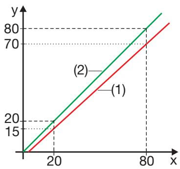
You can use customer-specific fine adjustment to correct the measured values of the sensor. In contrast to offsetting, which is used to specify a constant correction value for the entire characteristic line, fine adjustment can also be used to change the gradient of the characteristic line.
TIP
The actual start value and actual end value can also be selected with the teach function. The fine adjustment data are not stored in the parameter manager.
The data is transferred in a cycle via the IO-Link interface to the IO-Link master (PDI = Process Data Input). The entire process data can be extracted via index 40 and subindex 0.
| Designation | Data type | Default | Description |
|---|---|---|---|
| Pressure process value | TFLOAT or TINT32 | 0 | The "Data format" configuration parameter can be used to switch between data types. |
| Pressure process value unit | TUINT8 | bar | 0 = bar, 1 = mbar, 5 = psi, etc. |
| Pressure process value status | TUINT8 (bit field) | 0 | Bit 0 = Process value invalid Bit 1 = Error in configuration data Bit 2 = Error in calibration data |
| Switching output | TUINT8 (bit field) | 0 | Bit 0 = Switching output 1 Bit 1 = Switching output 2 (0 = Not switched, 1 = Switched) |
The configuration is stored in the parameter manager and is transferred via the IO-Link interface in an acyclic process.
| Designation | Index | Data type | Default | Access |
|---|---|---|---|---|
| Data format | 64 | TENUM (1 byte) | Floating point | RW |
| Pressure process value unit | 120 | TENUM (1 byte) | bar | RW |
| Pressure process value offset | 121 | TFLOAT | 0 | RW |
| Pressure filter time constant | 122 | TFLOAT | 0 | RW |
| Switching behavior (Out 1/2) | 200 / 201 | TENUM | Inactive | RW |
| Switching point/Window high | 200 / 201 | TFLOAT | 0 | RW |
| Release point/Window low | 200 / 201 | TFLOAT | 0 | RW |
| Switch-on delay | 200 / 201 | TFLOAT | 0 | RW |
| Switch-off delay | 200 / 201 | TFLOAT | 0 | RW |
| Output mode | 200 / 201 | TENUM (1 byte) | P-switching | RW |
IO-Link offers a range of fault signaling options (device status, event codes, PDValid-Flag). Malfunctions can also be signaled within the process data via the process value itself or the status of the process value.
| Description | Process value status in PDI | Device status | Event code | Event error type |
|---|---|---|---|---|
| Process value invalid | Bit0 (Process data invalid) | 4 (failure) | 0x1000 | Error |
| Overrange | Bit0 (Process data invalid) | 4 (failure) | 0x8C20 | Error |
| Underrange | Bit0 (Process data invalid) | 4 (failure) | 0x8C20 | Error |
| Error in configuration data | Bit1 (Parameter error) | 4 (failure) | 0x6320 | Error |
| Device is defective | Bit2 (Device is defective) | 4 (failure) | 0x5000 | Error |
| Undervoltage | - | 2 (Outside spec) | 0x5111 | Warning |
| Temperature error, overload | - | 4 (failure) | 0x4000 | Error |