

PN16

BURKERT 311625 (Type 8640) is a 10-station pneumatic valve block with 33 mm station width, 10 bistable 5/3-way valves, G 1/2 supply ports, G 1/4 working ports, and MP07 external auxiliary pilot air connection.
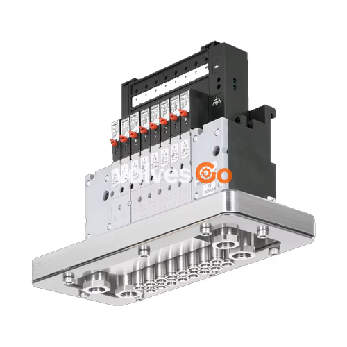
BURKERT 311625 (Type 8640) is a modular pneumatic valve block assembly configured with 10 valve stations at a width of 33 mm per station. Fitted with 10 bistable 5/3-way valves (Type 6519), the unit provides G 1/2 threaded supply and exhaust connections (P/R) and G 1/4 threaded working line ports (A/B). The assembly incorporates an external auxiliary pilot air connection (X) routed directly on the MP07 base module, delivering pneumatic control with an IP20 enclosure protection rating.
Type 8640 modular valve blocks assemble through interlocking base modules, end connection modules, and intermediate pneumatic feeds. The system channels pilot and supply air across adjacent stations through dedicated internal galleries sealed by elastomer profile seals and O-rings.
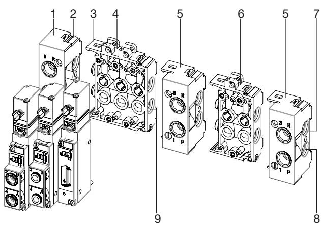
| Item | Designation | Functional Scope |
|---|---|---|
| 1 | Left connection module | Pneumatic supply header and mounting anchor |
| 2 | Latch tab | Mechanical interlock interface |
| 3 | Latch hook | Snapping retainer between sub-base segments |
| 4 | Base modules (3-fold) | Shared supply and exhaust base for multiple stations |
| 5 | Right connection module | Terminal module, expandable for dual-pressure stages |
| 6 | Base modules (2-fold) | Sub-base segment for pneumatic valve mounting |
| 7 | Exhaust channel 3(R) | Common vent passage for discharged pilot/working air |
| 8 | Supply channel 1(P) | Common main pressure channel |
| 9 | O-ring | Module interface airtight seal |
Module Assembly Sequence
Assembly starts from the left connection module. Verify that every module interface has two O-rings seated and lightly lubricated before engagement. Insert lower latch hooks into the preceding module's grooves, press upward slightly, and snap the upper latch hooks into position. Inspect the valve rear face for three O-rings prior to securing valves to the base with two screws at 0.6 ±0.1 Nm torque.
BURKERT 311625 operates within defined pneumatic pressure thresholds and fluid cleanliness standards.
| Parameter | Source Specification |
|---|---|
| Article Number | 311625 |
| System Type | 8640 |
| Width per Station | 33 mm |
| Valve Configuration | 10 positions with 10 bistable 5/3-way valves |
| Port P and R (Supply/Exhaust) | G 1/2 threaded port |
| Port A and B (Working Outlets) | G 1/4 threaded port |
| Auxiliary Control Air Port (X) | External connection directly on MP07 base |
| Ingress Protection Rating | IP20 |
| Operating Pressure Range | 2 to 10 bar |
| Pilot Pressure Range | 2 to 10 bar (minimum 70% of operating pressure) |
| Differential Pressure (Port 1 to 3) | Minimum 2 bar differential |
| Operating Medium | Filtered compressed air (particle size ≤ 10 μm), neutral gases (≤ 5 μm) |
| Ambient Temperature | -10 °C to +55 °C |
| Medium Temperature | -10 °C to +50 °C (restricted to dried air below 0 °C) |
| Seal Material | NBR |
Operating Pressure Limits
The pilot pressure for pneumatic activation must remain between 2 and 10 bar and never drop below 70% of the active operating pressure. Maintain at least 2 bar differential pressure between pressure port 1 and exhaust port 3. Below 0 °C, use dried air exclusively to prevent freezing inside the pilot chambers.
BURKERT 311625 supports direct wall mounting or standard DIN rail attachment. Any spatial installation orientation is permissible, with the solenoid actuator facing upward preferred.
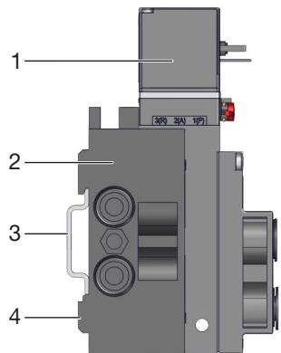
| Item | Designation | Mechanical Detail |
|---|---|---|
| 1 | Rotatable electrical interface | 180° reversible cable orientation |
| 2 | Wall mounting point | Fixed with M4 screws directly onto mounting surface |
| 3 | Standard rail | DIN rail 35 x 15 mm or 35 x 7.5 mm conforming to EN 50022 |
| 4 | Connection module | Lateral clamping and structural terminal |
For DIN rail attachment:
For wall installation, secure the block through the dedicated mounting holes using M4 screws.
Pneumatic supply, exhaust, and auxiliary lines connect to designated ports on the manifold block and valve bodies. All lines must be purged and free of debris prior to installation.
| Port Size | Designation / Marking | Recommended Torque | Maximum Permissible Torque |
|---|---|---|---|
| G 1/4 | Valve working outlets A/B | 4 to 7 Nm | 20 Nm |
| G 1/8 | Working outlets / auxiliary lines | 3 to 6 Nm | 7 Nm |
| G 1/2 | Main supply P and exhaust R | Thread sealant applied | Thread sealant applied |
Flexible tubing connected via push-in fittings must meet DIN 53505 or ISO 868 standards with a minimum hardness of 40 Shore D. Tubing outer diameter must follow DIN 73378 within ±0.1 mm tolerance. Cuts must be perpendicular, clean, and burr-free.
Push-in connections comply with ISO 14743:2020 retention force criteria:
| Hose Outer Diameter (OD) | 3 mm (1/8") | 4 mm (5/32") | 6 mm (1/4") | 8 mm (5/16") | 10 mm (3/8") | 12 mm (1/2") | 14 mm | 16 mm (5/8") |
|---|---|---|---|---|---|---|---|---|
| Min. Tensile Force (PA tubing) | 60 N | 70 N | 120 N | 170 N | 250 N | 300 N | 300 N | 350 N |
| Min. Tensile Force (PU tubing) | 25 N | 50 N | 100 N | 150 N | 200 N | 200 N | 250 N | 300 N |
Tubing Retention with Flexible Lines
When using softer polyurethane (PU) tubing under high thermal or mechanical loads, insert support sleeves (ID 20099400) into the tube ends prior to insertion to prevent collapse and leakage.
When electrical connectors are installed on individual pilot coils, Type 2516 cable plugs conforming to DIN EN 175301-803 Form C are used.
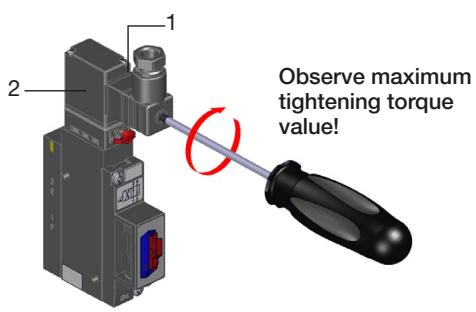
Fasten the cable plug screw with a maximum tightening torque of 0.3 Nm, verifying that the flat seal is seated squarely between the plug and the coil socket. Check electrical ground continuity between the coil housing and the ground terminal: resistance must not exceed 0.1 Ω at a test current of 1 A and test voltage of 12 V.
For pulse-driven pilot coils, adhere to correct pin polarity as indicated on the coil casing, maintaining a pulse duration of at least 50 ms.

| Item | Label Field | Source Data Example |
|---|---|---|
| 1 | Type, circuit function, orifice | Type 5470 / 6519, function code, orifice size |
| 2 | Port connection, pressure range | G connection, PN 2-10 bar |
| 3 | Electrical voltage and power | Operating voltage, coil wattage |
| 4 | Article identification | 8-digit article number and encrypted manufacture date code |
Before commissioning, verify that line pressures do not exceed 10 bar, pneumatic supply lines 1 and 3 are correctly assigned, and all manual overrides are returned to their zero position.
| Fault Observed | Possible Root Cause | Corrective Action |
|---|---|---|
| Valves fail to actuate | Insufficient operating pressure (< 2 bar) | Verify primary compressor supply; confirm supply pressure ≥ 2 bar |
| Manual override locked in active position | Return manual override to its neutral zero position | |
| Control voltage missing or insufficient | Check electrical supply and wiring pins against type label | |
| Delayed switching or continuous venting | Air applied while valves were energized | Pressurize the valve block before switching individual valves |
| Silencer dirty or undersized | Install adequately sized silencer; clean existing exhaust elements | |
| Particulate contamination in pilot stage | Apply pulsed air bursts through exhaust line or clean pilot seat | |
| Leakage across valve stations | O-rings missing or pinched between modules | Inspect inter-module joints; replace damaged or pinched O-rings |
| Displaced flat seal under valve body | Realign or replace sub-base flat gasket; retorque screws to 0.6 Nm |
To disassemble the valve island, vent all compressed air lines, disconnect electrical supplies, loosen rail clamp screws by approximately 4 turns, and lift the assembly clear of the DIN rail. Tube lines are removed by depressing the push-in thrust collar while pulling the tubing outward.
Explore similar products in our catalog


