PN25

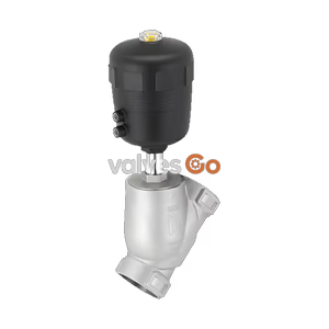
BURKERT 20133488 (Type 2060) is a pneumatically operated 2/2-way stainless steel angle seat valve, DN20 RC 3/4", normally open (CF B), rated -0.9 to 16 bar and -10 to +185 °C for gases, steam, and liquids.
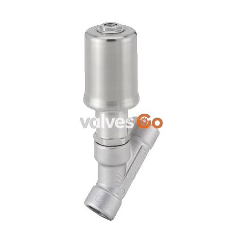
BURKERT 20133488 (Type 2060) is a pneumatically operated 2/2-way angle seat valve equipped with a laser-welded stainless steel piston actuator, designed for demanding media and washdown process environments. The valve features an internal RC 3/4" (ISO 7-1) threaded port connection with a DN 20 nominal diameter and 20 mm seat orifice. Operated under Control Function B (CF B), the valve is held normally open by internal spring force and driven closed by pneumatic pilot air routed through port 2. The flow path is configured below the valve seat, allowing safe operation with liquids, gases, and steam without the risk of water hammer.
Engineered with an operating pressure rating from -0.9 bar(g) to 16 bar(g) and a medium temperature envelope from -10 °C to +185 °C, Burkert 20133488 incorporates a solid PTFE seat seal providing Leakage Rate A tight shut-off per DIN EN 12266-1. The self-adjusting spindle packing gland uses spring-compensated PTFE V-rings to maintain stem sealing integrity over extended operational cycles. The unit delivers a water flow coefficient Kv of 10 m³/h at +20 °C with 1 bar pressure drop. All wetted metallic and elastomeric components conform to EC Regulation 1935/2004 for food contact and support automated Clean-in-Place (CIP) and Sterilization-in-Place (SIP) routines.
| Specification Parameter | Technical Value |
|---|---|
| Valve Identification | Burkert Type 2060 (Article No. 20133488) |
| Valve Construction | Complete 2/2-way angle seat valve with piston actuator |
| Port Connection Type | Internal pipe thread RC (ISO 7-1) |
| Port Thread Marking | RC 3/4" |
| Nominal Diameter (DN / NPS) | DN 20 (NPS 3/4") |
| Seat Orifice Diameter | 20 mm |
| Flow Coefficient Kv (Water) | 10 m³/h (+20 °C, 1 bar Δp across valve) |
| Control Function | B (CF B): Normally open by spring force, closes pneumatically |
| Flow Direction | Below seat (flow to open) |
| Operating Pressure Range | -0.9 bar(g) to 16 bar(g) (vacuum version without leakage bore) |
| Nominal Pressure Class | PN 25 (DIN EN 1333) / Class 150 (DIN EN 1759) |
| Pilot Pressure Range | 2.0 bar(g) to 10.5 bar(g) (Actuator size 50 D) |
| Medium Temperature Range | -10 °C to +185 °C (continuous) |
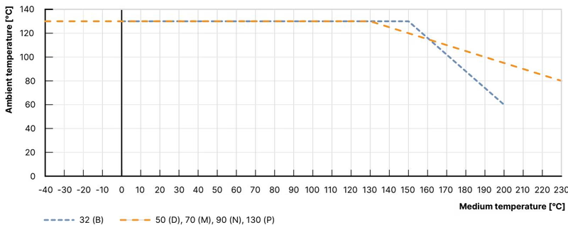
| Ambient Temperature Range | 0 °C to +130 °C (device limit -10 °C to +130 °C) |
| Maximum Fluid Viscosity | 600 mm²/s |
| Pilot Medium | Neutral gases, instrument compressed air |
| Pilot Air Connection | G 1/8" internal thread bushing |
| Body Material | Cast stainless steel CF3M (316L equivalent) |
| Actuator Housing Material | Stainless steel 1.4404 (316L) |
| Seat Seal Material | PTFE (Polytetrafluoroethylene) |
| Piston Seal Material | FKM (Fluor rubber) |
| Spindle Seal | PTFE V-rings (filled), spring-compensated |
| Spindle Guide | Filled PTFE (Actuator size 50 D) |
| Seat Leakage Performance | Leakage rate A according to DIN EN 12266-1 (test medium air) |
| Degree of Protection | IP65 / IP67 |
| Food Contact Compliance | EC Regulation 1935/2004 compliant manufacturer declaration |
| CIP / SIP Capability | Yes (steam sterilization up to 140 °C / 185 °C continuous rating) |
Burkert Type 2060 actuator size 50 (D) utilizes a laser-welded stainless steel housing that eliminates external contamination traps and permits deployment in corrosive atmospheres or washdown environments. A transparent polysulfone hood provides visual position indication, while internal components are constructed from corrosion-resistant austenitic stainless steels and technical polymers.
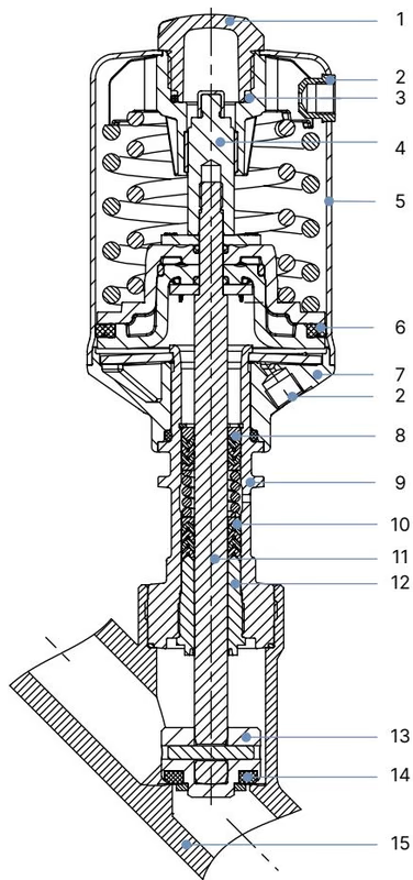
| Item No. | Valve Element | Material Specification |
|---|---|---|
| 1 | Transparent cover (visual position indicator) | Polysulfone PSU |
| 2 | Pilot air connection port | Threaded bushing G 1/8" stainless steel 1.4404 (316L) |
| 3 | Spring support | Stainless steel 1.4308 |
| 4 | Spindle extension | Stainless steel 1.4104 |
| 5 | Actuator casing | Stainless steel 1.4404 (316L) |
| 6 | Piston seal | FKM |
| 7 | Actuator base interface | Stainless steel 1.4308 |
| 8 | Return spring | Stainless steel 1.4310 |
| 9 | Pipe / bonnet neck | Stainless steel 1.4401 (316) / 1.4404 (316L) |
| 10 | Spindle packing gland | Filled PTFE V-rings with spring compensation |
| 11 | Valve spindle | Stainless steel 1.4401 (316) / 1.4404 (316L) |
| 12 | Spindle guide | Filled PTFE (Actuator size 50 D) |
| 13 | Swivel plate | Stainless steel 1.4401 (316) / 1.4404 (316L) |
| 14 | Seat seal | PTFE (Polytetrafluoroethylene) |
| 15 | Valve body | Stainless steel CF3M |
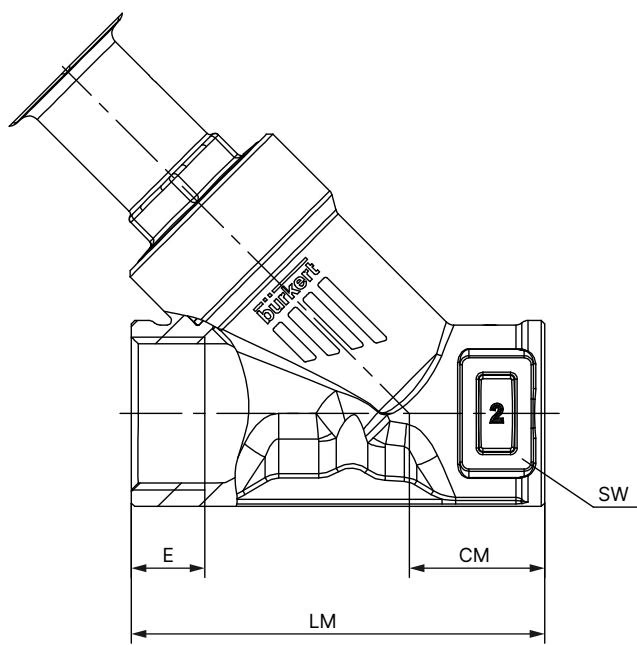
Physical dimensions for Burkert Type 2060 with actuator size 50 (D) and threaded body connections conform to metric pipeline engineering standards.
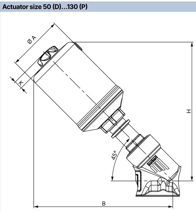
| DN | NPS | Actuator Size | Ø A [mm] | B/H max [mm] | K [mm] | Pilot Port P |
|---|---|---|---|---|---|---|
| 10 | 3/8" | 32 (B) | 36.4 | 89.4 | 8.6 | M5 |
| 15 | 1/2" | 32 (B) | 36.4 | 96.0 | 8.6 | M5 |
| 15 | 1/2" | 50 (D) | 55.0 | 154.0 | 11.0 | G 1/8 |
| 15 | 1/2" | 70 (M) | 75.0 | 174.0 | 11.0 | G 1/8 |
| 20 | 3/4" | 50 (D) | 55.0 | 157.0 | 11.0 | G 1/8 |
| 20 | 3/4" | 70 (M) | 75.0 | 180.0 | 11.0 | G 1/8 |
| 25 | 1" | 50 (D) | 55.0 | 169.0 | 11.0 | G 1/8 |
| 25 | 1" | 70 (M) | 75.0 | 184.0 | 11.0 | G 1/8 |
| 25 | 1" | 90 (N) | 96.0 | 233.0 | 14.0 | G 1/8 |
| 32 | 1 1/4" | 70 (M) | 75.0 | 193.0 | 11.0 | G 1/8 |
| 32 | 1 1/4" | 90 (N) | 96.0 | 238.0 | 14.0 | G 1/8 |
| 32 | 1 1/4" | 130 (P) | 137.0 | 283.0 | 14.0 | G 1/8 |
| 40 | 1 1/2" | 70 (M) | 75.0 | 196.0 | 11.0 | G 1/8 |
| 40 | 1 1/2" | 90 (N) | 96.0 | 242.0 | 14.0 | G 1/8 |
| 40 | 1 1/2" | 130 (P) | 137.0 | 286.0 | 14.0 | G 1/8 |
| 50 | 2" | 70 (M) | 75.0 | 214.0 | 11.0 | G 1/8 |
| 50 | 2" | 90 (N) | 96.0 | 257.0 | 14.0 | G 1/8 |
| 50 | 2" | 130 (P) | 137.0 | 301.0 | 14.0 | G 1/8 |
| 65 | 2 1/2" | 90 (N) | 96.0 | 269.0 | 11.0 | G 1/8 |
| 65 | 2 1/2" | 130 (P) | 137.0 | 314.0 | 14.0 | G 1/8 |
| 80 | 3" | 130 (P) | 137.0 | 334.0 | 14.0 | G 1/8 |
Note: Dimensions B/H and K represent maximum values and may decrease by up to 6 mm depending on port connection standard.
| DN | NPS | E [G] (mm) | E [NPT] (mm) | E [RC] (mm) | CM (mm) | LM (mm) | SW (mm) |
|---|---|---|---|---|---|---|---|
| 10 | 3/8" | 12.0 | 10.3 | 10.1 | 18.5 | 65.0 | — |
| 15 | 1/2" | 14.0 | 13.7 | 13.2 | 24.0 | 65.0 | 27 |
| 20 | 3/4" | 16.0 | 14.0 | 14.5 | 27.0 | 75.0 | 34 |
| 25 | 1" | 18.0 | 16.8 | 16.8 | 29.5 | 90.0 | 41 |
| 32 | 1 1/4" | 16.0 | 17.3 | 19.1 | 36.0 | 110.0 | 50 |
| 40 | 1 1/2" | 18.0 | 17.3 | 19.1 | 35.0 | 120.0 | 55 |
| 50 | 2" | 24.0 | 17.6 | 23.4 | 45.0 | 150.0 | 70 |
| 65 | 2 1/2" | 26.0 | 23.7 | 26.7 | 57.0 | 185.0 | 85 |
| 80 | 3" | 28.0 | — | — | 71.0 | 220.0 | 100 |
Burkert 20133488 directs process media below the seat disc. This flow path uses upstream process pressure to assist the mechanical spring force during opening, ensuring stable operation with compressible and non-compressible media.
Risk of Pipe Rupture from Flow Above Seat
When operating with flow above the seat disc, closing against liquid media can generate severe water hammer, leading to fractured pipework and device destruction. Valves configured for flow above the seat must never be used with liquid media. Model 20133488 routes flow below the seat, making it fully safe for liquids, steam, and gases.
| DN | NPS | Seat DN | Actuator Size | Kv Water [m³/h] | Min Pilot Press. [bar(g)] | Max Operating Pressure (CF A PTFE) | Max Operating Pressure (CF A PEEK) | Max Operating Pressure (CF B PTFE) |
|---|---|---|---|---|---|---|---|---|
| 10 | 3/8" | 10 | 32 (B) | 2.4 | 5.5 | 16 bar | — | 16 bar |
| 8 | 1/4" | 15 | 32 (B) | 2.6 | 5.5 | 11 bar | — | 16 bar |
| 8 | 1/4" | 15 | 50 (D) | 2.6 | 4.1 | 16 bar | — | 16 bar |
| 8 | 1/4" | 15 | 70 (M) | 2.6 | 4.8 | 25 bar | 25 bar | 25 bar |
| 10 | 3/8" | 15 | 32 (B) | 4.7 | 5.5 | 11 bar | — | 16 bar |
| 10 | 3/8" | 15 | 50 (D) | 5.3 | 4.1 | 16 bar | — | 16 bar |
| 10 | 3/8" | 15 | 70 (M) | 5.4 | 4.8 | 25 bar | 25 bar | 25 bar |
| 15 | 1/2" | 15 | 32 (B) | 4.7 | 5.5 | 11 bar | — | 16 bar |
| 15 | 1/2" | 15 | 50 (D) | 5.3 | 4.1 | 16 bar | — | 16 bar |
| 15 | 1/2" | 15 | 70 (M) | 5.4 | 4.8 | 25 bar | 25 bar | 25 bar |
| 20 | 3/4" | 20 | 50 (D) | 10.0 | 2.0–10.5 | 11 bar | 8.5 bar | 16 bar |
| 20 | 3/4" | 20 | 70 (M) | 11.0 | 4.8 | 25 bar | 25 bar | 25 bar |
| 25 | 1" | 25 | 50 (D) | 15.0 | 4.1 | 5.2 bar | — | 16 bar |
| 25 | 1" | 25 | 70 (M) | 20.0 | 4.8 | 16 bar | 13.5 bar | 25 bar |
| 25 | 1" | 25 | 90 (N) | 21.0 | 5.0 | 25 bar | 25 bar | 25 bar |
| 32 | 1 1/4" | 32 | 70 (M) | 30.0 | 4.8 | 8.5 bar | — | 25 bar |
| 32 | 1 1/4" | 32 | 90 (N) | 30.0 | 5.0 | 25 bar | 19.5 bar | 25 bar |
| 40 | 1 1/2" | 40 | 70 (M) | 40.0 | 4.8 | 6.0 bar | — | 25 bar |
| 40 | 1 1/2" | 40 | 90 (N) | 44.0 | 5.0 | 16 bar | 13.5 bar | 25 bar |
| 40 | 1 1/2" | 40 | 130 (P) | 47.0 | 5.0 | 25 bar | 25 bar | 25 bar |
| 50 | 2" | 50 | 90 (N) | 55.0 | 5.0 | 10 bar | — | 25 bar |
| 65 | 2 1/2" | 65 | 90 (N) | 82.0 | 5.0 | 5.0 bar | — | 11 bar |
| 80 | 3" | 80 | 130 (P) | 140.0 | 5.6 | 10 bar | 8.0 bar | 11 bar |
Process pressure capability varies directly with fluid temperature according to international piping standards. The diagrams and derating tables define allowable operational boundaries.
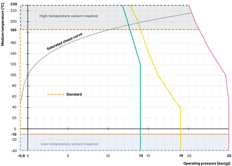
| Temperature [°C] | Max Pressure PN25 (DIN EN 12516-1) | Max Pressure Class 150 (ASME B16.34) | Max Pressure 10K (JIS B 2220) |
|---|---|---|---|
| -10 to +38 °C | 25.0 bar | 19.0 bar (-29 to +38 °C) | 14.0 bar |
| +50 °C | 25.0 bar | 18.4 bar | 14.0 bar |
| +100 °C | 24.5 bar | 16.2 bar | 14.0 bar |
| +150 °C | 22.4 bar | 14.8 bar | 13.4 bar |
| +185 °C (Burkert 20133488) | 21.0 bar (interpolated) | 14.1 bar (interpolated) | 12.8 bar (interpolated) |
| +200 °C | 20.3 bar | 13.7 bar | 12.4 bar |
| +230 °C | 19.0 bar | 12.7 bar | 11.7 bar |
Installation must be performed by qualified personnel using open-end wrenches on specified flats. Before piping installation, verify that connecting pipelines are aligned axially and purged of welding slag and particulates.
360° Rotatable Pneumatic Connection
The stainless steel actuator can be steplessly rotated through 360° around the valve body axis. This permits precise positioning of the pilot air ports to accommodate hose routing without loosening process pipe joints.
| Valve Orifice Size (DN) | Assembly Tightening Torque [Nm] |
|---|---|
| DN 15 | 45 ± 3 Nm |
| DN 20 (Burkert 20133488) | 50 ± 3 Nm |
| DN 25 | 60 ± 3 Nm |
| DN 32 | 65 ± 3 Nm |
| DN 40 | 65 ± 3 Nm |
| DN 50 | 70 ± 3 Nm |
| DN 65 | 100 ± 3 Nm |
When installing the valve in systems conforming to DIN EN 161 ("Automatic shut-off valves for gas burners and gas appliances"), a strainer or dirt trap preventing penetration of a 1 mm test pin must be installed directly upstream.
Connect the pilot medium (instrument air, 2.0 to 10.5 bar) to pilot air port 2 for Control Function B. Pilot air hoses of sizes 6/4 mm or 1/4" are recommended. Install a silencer into unpressurized exhaust port 1 to reduce venting noise and exclude external contamination.
The stainless steel piston actuator is maintenance-free under normal operating conditions. Regular visual checks should inspect fluid line connections for external leakage and examine the relief bore on the bonnet neck.
Actuator Size 50 (D) Packing Gland Service Restriction
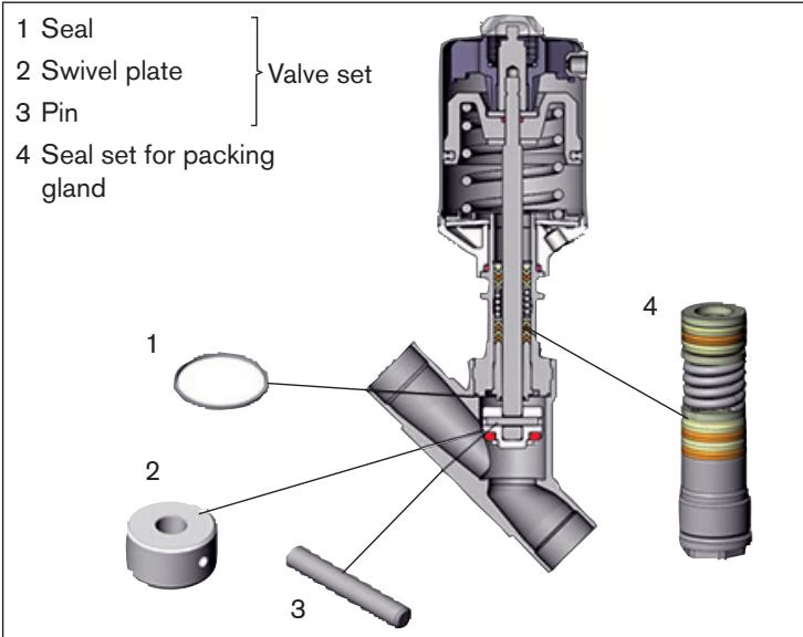
According to Burkert operating instructions section 9.2.2, angle seat valves configured with actuator size 50 (D)—including Article 20133488—or size 70 (M) on DN 50 bodies do not support independent field replacement of the packing gland. When stem leakage occurs through the relief bore, replace the complete actuator assembly. The seat seal and swivel plate assembly (valve set) remains fully replaceable in the field.
| Valve Body Size (DN) | Valve Set Order Number (PTFE Seat Seal) |
|---|---|
| DN 15 | 011 134 |
| DN 20 (Burkert 20133488) | 011 171 |
| DN 25 | 160 737 |
| DN 32 | 011 208 |
| DN 40 | 011 209 |
| DN 50 | 216 431 |
| DN 65 | 241 777 |
Burkert Type 2060 pairs with modular accessories to provide discrete position feedback, mechanical stroke adjustment, and automated system integration.
| Accessory Description | Applicable Actuator Size | Order Code |
|---|---|---|
| Stainless steel silencer kit (silencer + PTFE seal ring) | Universal (G 1/8) | 696931 |
| Maximum stroke limiter | Ø 50 (D), Ø 70 (M) | 699550 |
| Minimum and maximum stroke limiter | Ø 50 (D), Ø 70 (M) | 699986 |
| Single inductive proximity switch bracket kit | Ø 50 (D), Ø 70 (M) | 699989 |
| Dual inductive proximity switch bracket kit | Ø 50 (D), Ø 70 (M) | 699990 |
| Adapter kit for Type 8697 position feedback | Ø 50 (D), Ø 70 (M) | 699551 |
| Type 8697 pneumatic control / position feedback unit | Universal | on request |
Combining Burkert Type 2060 with the Type 8697 position feedback head creates the factory-tested Type 8801-YV on/off ELEMENT valve system, featuring integrated mechanical or inductive limit switches, LED status display, and IP65/IP67 enclosure protection.
Explore similar products in our catalog