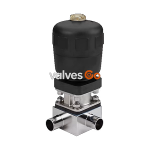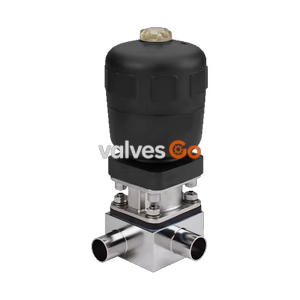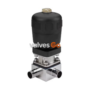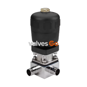
Type 2032

The Burkert Type 2935 is a manually operated tank bottom diaphragm valve featuring a flow-optimized stainless steel body, zero dead volume, and hygienic approvals including FDA, USP Class VI, and 3-A.
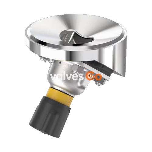
Burkert Type 2935 manually operated diaphragm valve consists of a manually operated actuator, a diaphragm, and a tank bottom valve body. The manual actuator with a plastic or stainless steel handwheel is available with a diaphragm bonnet made of stainless steel or plastic, ensuring suitability for hygienic or aggressive ambient conditions. The flow-optimized valve body with minimum dead space enables high flow values and a wide range of possible applications.
The actuator has a compact, autoclavable design and is compatible with all other Bürkert diaphragm valves. An explosion-proof ATEX/IECEx device variant is available. The manual actuator is equipped with an integrated visual position indicator, a reproducible stroke scale, and an adjustable closing limiter.
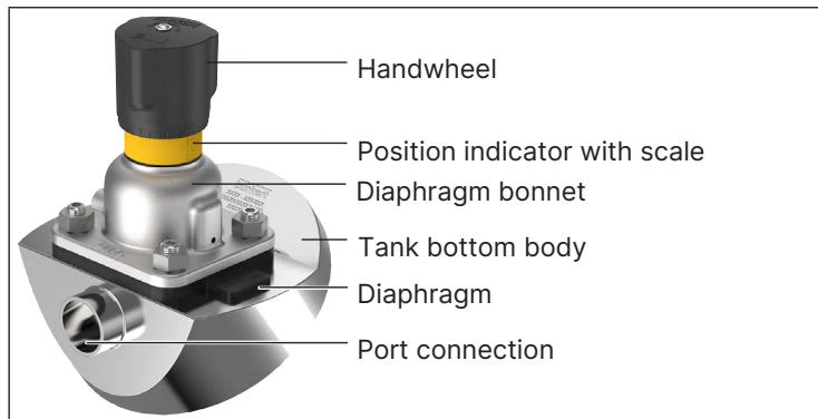
| Product properties | Description |
|---|---|
| Block body (VH/VI) | Stainless steel block material 1.4435 according to DIN EN 10088 and 316L according to ASTM A479 / A479M / ASME BPE |
| Diaphragm | EPDM (AD), PTFE/EPDM (EA), advanced PTFE/EPDM (EU), laminate of GYLON® and EPDM (ER) |
| Actuator | Stainless steel/PPS, PPS/PPS, stainless steel/stainless steel |
| Diaphragm size | 8...100 |
| Standard surface quality | Internally electrically polished: Ra ≤ 0.38 μm (ASME BPE SF4/DIN HE4) Internally mechanically polished: Ra ≤ 0.5 μm (ASME BPE SF1) (externally: Ra ≤ 1.6 μm) |
| Operating medium | Neutral gases and liquids, highly purified, sterile, aggressive or abrasive mediums |
| Nominal diameter | DN 06...DN 100 (1/8"...4") |
| Ambient temperature | -10...+130 °C (short-term up to + 150 °C), autoclavable |
| Material | Temperature Range |
|---|---|
| EPDM (AD) | -10...+143 °C (steam sterilisation + 150 °C for 60 min) |
| PTFE/EPDM (EA) | -10...+130 °C (steam sterilisation + 140 °C for 60 min) |
| Advanced PTFE/EPDM (EU) | -5...+143 °C (steam sterilisation + 150 °C for 60 min) |
| Laminate of GYLON® and EPDM (ER) | -5...+130 °C (steam sterilisation + 140 °C for 60 min) |
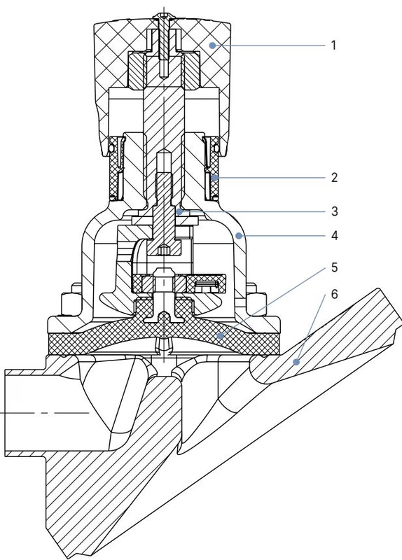
| No. | Element | Material |
|---|---|---|
| 1 | Handwheel | Polyphenylene sulphide (PPS), stainless steel 1.4308 |
| 2 | Visual position indicator | Polyamide (PA), stainless steel 1.4305 |
| 3 | Valve spindle | Stainless steel 1.4305 |
| 4 | Diaphragm bonnet | Stainless steel 1.4308, polyphenylene sulphide (PPS) |
| 5 | Diaphragm | EPDM (AD), PTFE/EPDM (EA), advanced PTFE/EPDM (EU), laminate of GYLON® and EPDM (ER) |
| 6 | Valve body | Stainless steel block material |
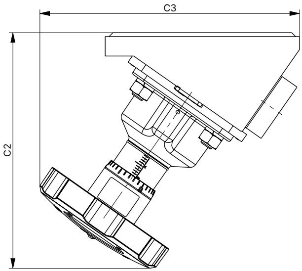
| Diaphragm size | C2 | C3 |
|---|---|---|
| 8 | 69 | 71 |
| 15 | 103 | 101 |
| 20 | 116 | 115 |
| 25 | 127 | 129 |
| 40 | 182 | 201 |
| 50 | 203 | 217 |
| 65 | 265 | 305 |
| 80 | 336 | 278 |
| 100 | 300 | 370 |
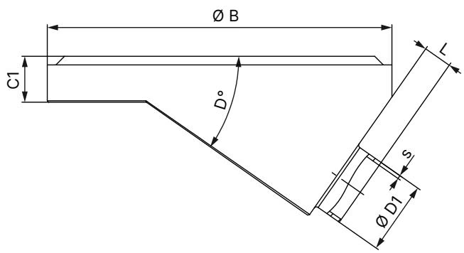
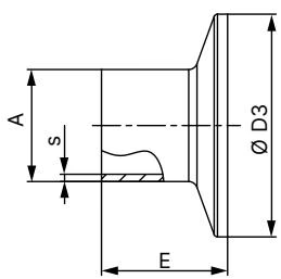
(Dimensions in mm, unless otherwise stated. Refer to the full datasheet for comprehensive dimensional tables covering DIN EN ISO 1127, DIN 11850, ASME BPE, and SMS 3008 standards.)
INFO
Clamp dimensions must be added to the welded connection dimensions.
| Diaphragm size | Maximum static operating pressure [bar] | Tightening torque EPDM, FKM [Nm] | Tightening torque PTFE/EPDM, advanced PTFE/EPDM, GYLON® [Nm] |
|---|---|---|---|
| 8 | 10 | 0.6 | 1.1 |
| 15 | 10 | 0.8 | 1.7 |
| 20 | 10 | 0.9 | 3 |
| 25 | 10 | 1.2 | 3.5 |
| 32 | 10 | 2.5 | 4 |
| 40 | 10 | 4.5 | 7 |
| 50 | 10 | 6 | 11 |
| 65 | 10 | 8 | 21 |
| 80 | 10 | 12 | 23 |
| 100 | 10 | 13 | 24 |
WARNING
The tightening torques refer to the static media pressures specified above. Excessive torque can shorten the service life of the diaphragm. A tolerance of + 10 % applies to the tightening torques specified.
DANGER
Risk of injury due to high pressure and escaping medium. Switch off the pressure before working on the device or system. Vent or empty the lines.
Observe the following sequence:
Ensure that pipelines are in alignment. Support and align pipelines. To ensure that the pipeline is self-draining, we recommend the inclination angles according to the valid ASME BPE.
Recommendations
For information on containers and instructions for welding, refer to the ASME VIII Division I standard. Check the batch number indicated on the manufacturer’s certificate 3.1 supplied before starting welding work.
WARNING
Before welding, note the following:
When used in accordance with the operating instructions, the actuator of the diaphragm valve is maintenance-free.
Explore similar products in our catalog