PN25

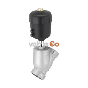
BURKERT 20127603 (Type 2101) is a pneumatically operated 2/2-way flanged globe valve with DN 25 port size, PN 25 rating, normally open CFB function, stainless steel body, PTFE seat seal, and ATEX/IECEx approval.
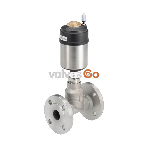
BURKERT 20127603 (Type 2101) is a pneumatically operated 2/2-way globe valve engineered for plant isolation and automated process control. Configured with control function B (normally open, CFB), the valve remains open in its resting state via spring force and closes when pilot air pressure is applied. Media flow enters below the seat, so pipeline operating pressure helps the valve open and prevents pressure hammer in liquid or gaseous delivery systems. The unit integrates a 316L stainless steel valve body, DIN EN 1092-1 PN 25 flanged pipe ports, a nominal seat orifice of DN 25, a Kv value of 13 m³/h, and a polyphenylene sulphide (PPS) ELEMENT piston actuator.
Operating capabilities span a medium temperature range from -10 °C to +185 °C and an operating pressure range from -0.9 bar vacuum up to 25 bar. Sealing integrity is provided by a PTFE seat seal on a stainless steel swivel plate alongside a self-adjusting PTFE V-ring spindle packing gland with integrated spring compensation. The assembly complies with ATEX and IECEx standards for mechanical equipment in explosive gas and dust atmospheres (Zones 1, 21, 2, and 22), meets EC 1935/2004 food contact regulations, and supports CIP (Clean-in-Place) and SIP (Steam-in-Place) sterilization cycles.
Type 2101 consists of a pneumatically operated piston actuator coupled directly to a 2-way valve body. The valve body incorporates a screwed-in stainless steel valve seat that can be replaced or resized during servicing. A spindle transmits thrust from the actuator piston to an articulated stainless steel swivel plate fitted with a PTFE seal disc.

In control function B (CFB), internal compression springs hold the valve disc away from the seat when pilot pressure is vented, securing full flow across the port. Applying pilot pressure to the actuator pilot air port pushes the piston downward against spring tension, seating the swivel plate onto the orifice.

Because media travels upward from below the seat, fluid pressure acts beneath the swivel plate. This arrangement assists valve opening, stabilizes shut-off closure against liquid velocity, and prevents destructive pressure surges associated with flow-over-seat shut-off geometries in liquid lines.
Pressure Surge Hazard
Valves with flow direction above the seat must not be used for liquid media due to hydraulic shock and line rupture risks. BURKERT 20127603 is factory-configured for flow below the seat, which is compatible with liquid and gaseous duties.
| Technical Parameter | Specification / Limit |
|---|---|
| Valve Type | 2/2-way globe valve Type 2101 |
| Article Number (MPN) | 20127603 |
| Port Connection Size | DN 25 flanged connection |
| Seat Orifice Diameter | 25 mm |
| Flow Coefficient (Kv) | 13 m³/h (water at +20 °C) |
| Flange Standard & Pressure Class | DIN EN 1092-1 PN 25 / Class 150 |
| Operating Pressure Range | -0.9 bar to 25 bar |
| Control Medium | Neutral gases, filtered instrument air |
| Pilot Pressure Range | 2.5 bar to 10 bar |
| Medium Temperature Range | -10 °C to +185 °C (PTFE seat) |
| Ambient Temperature Range | -10 °C to +100 °C |
| Valve Body Material | Stainless steel 316L |
| Actuator Material | Polyphenylene sulphide (PPS) |
| Swivel Plate & Spindle Material | Stainless steel 1.4401 / 1.4404 |
| Spindle Seal System | PTFE V-rings with spring compensation (silicone grease lubricated) |
| Seat Seal Material | PTFE (Polytetrafluorethylene) |
| Ingress Protection | IP67 per IEC 529 / EN 60529 |
| Compatible Media | Water, alcohols, fuels, hydraulic fluids, saline solutions, lyes, organic solvents, steam |
Operating pressure limits decrease as pipeline temperature rises. Under DIN EN 12516-1 (PN 25 rating) and ASME B16.5 / B16.34 Class 150, the permissible line pressure for stainless steel flanged bodies follows the table below:
| Medium Temperature | Permissible Operating Pressure (DIN EN 12516-1 PN 25) | Permissible Operating Pressure (ASME B16.5 Cl.150) |
|---|---|---|
| -29 °C to +38 °C | 25.0 bar | 19.0 bar |
| -10 °C to +50 °C | 25.0 bar | 18.4 bar |
| +100 °C | 24.5 bar | 16.2 bar |
| +150 °C | 22.4 bar | 14.8 bar |
| +185 °C | 20.9 bar | 14.0 bar |
| +200 °C | 20.3 bar | 13.7 bar |
| +230 °C | 19.0 bar | 12.7 bar |
BURKERT 20127603 conforms to European Directive 2014/34/EU and the IECEx scheme for non-electrical equipment operating in potentially explosive environments (Category 2 mechanical equipment, Zones 1 and 21, Zones 2 and 22). Certification markings are:
EPS 18 ATEX 2 008 X: II 2 G Ex h IIC T4...T2 Gb / II 2 D Ex h IIIC T135°C...T300°C DbIECEx EPS 18.0007 X: Ex h IIC T4...T2 Gb / Ex h IIIC T135°C...T300°C Db| Temperature Class | Maximum Permissible Surface Temperature | Permissible Ambient Temperature | Maximum Permissible Medium Temperature |
|---|---|---|---|
| T4 | 135 °C | -40 °C to +100 °C | 125 °C |
| T3 | 200 °C | -40 °C to +130 °C | 185 °C |
| T2 | 300 °C | -40 °C to +130 °C | 285 °C |
Electrostatic Discharge Hazard
Electrostatic accumulation on external non-metallic surfaces presents an ignition risk in explosive atmospheres. Clean the actuator housing only with a damp or antistatic cloth. Do not use dry wipes. The valve body and all conductive assemblies must be connected to the plant equipotential bonding circuit.
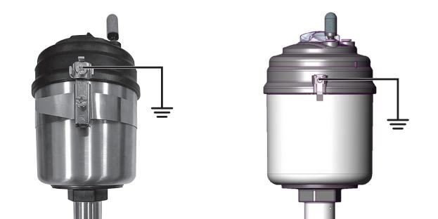
In accordance with IEC 60079-32-1, process media conductivity must be observed when operating in hazardous zones: media with conductivity ≤100 pS/m requires flow velocities ≤1 m/s and dry-run prevention; media between 100 pS/m and 1,000 pS/m is limited to particle-free fluids, steam, or pure gases; media with conductivity >1,000 pS/m can be transferred without fluid-velocity restriction.
Pipe connections require alignment of the mating DIN EN 1092-1 counter-flanges without mechanical stress. When welding companion pipe flanges, do not expose the mounted valve body or actuator to welding heat.
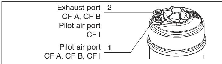
Pneumatic supply connects to pilot air port 1 using 6/4 mm or 1/4" hose via the 6 mm ELEMENT interface. In control function B, pressurizing port 1 closes the valve. A silencer must be installed on the venting port 2 to reduce discharge sound and exclude environmental contamination.
Actuator Alignment via 360° Rotation
The actuator housing can be rotated counterclockwise by 360° to optimize pneumatic port orientation. To adjust orientation without damaging the seat, apply 5 bar pilot air pressure to port 1 to bring the valve into the open position, engage an open-end wrench on the body connection hexagon, and rotate counterclockwise (viewed from below) to the target angle.
The spindle neck features an integrated relief bore for leakage detection and fluid discharge. On DN 25 assemblies, the relief bore has an M4x0.35 internal thread and includes an M5x0.8 thread adapter. When attaching a leakage monitoring sensor or tube fitting:
The PPS actuator is maintenance-free under normal operating conditions. Regular visual inspection of the spindle relief bore confirms packing gland integrity; if fluid emerges from the bore, replace the spindle seal packing.
| Component Connection | Nominal Size / Thread | Tightening Torque |
|---|---|---|
| Valve Body to Actuator Connection | DN 25 | 60 ± 3 Nm |
| Screwed-in Valve Seat | DN 25 | 40 ± 5 Nm |
| Spindle Guide Bushing (10 mm spindle) | DN 25 | 6 Nm |
| Spare Part / Tool Set | Component Description | Order Number |
|---|---|---|
| Valve Set DN 25 | Swivel plate with PTFE seal, locking pin, body seal | 160 737 |
| Valve Seat Set DN 25 | Screwed-in valve seat, O-ring, body seal | 262 170 |
| Packing Gland Seal Set | Chevron seals, spring, collars, guide, lubricant (standard) | 216 433 |
| Packing Gland Set (Water to 200 °C) | High-temperature hot water packings | 372 661 |
| Valve Seat Assembly Tool | Socket tool for DN 25 screwed seat | 652 606 |
| Modified Socket Wrench | Wrench AF 19 for 10 mm spindle guide | 683 221 |
Maintenance Safety Notice
Always depressurize process piping and vent actuator pilot pressure before loosening body connections. Open the valve with 5 bar pilot air pressure prior to unthreading the actuator from the body to protect the PTFE seat disc from rotational shear against the seat orifice.
| Fault Condition | Probable Root Cause | Corrective Action |
|---|---|---|
| Actuator does not switch | Pilot air port reversed | Connect pilot pressure to port 1 for control function B |
| Pilot pressure below 2.5 bar minimum | Increase control pressure to required level (2.5 bar to 10 bar) | |
| Operating line pressure exceeds 25 bar | Verify system operating pressure complies with rating label | |
| Reversed medium flow direction | Orient body so flow arrow points under the seat | |
| Valve seat leakage | Debris between seal disc and seat | Flush line; install upstream strainer (<1 mm per DIN EN 161) |
| PTFE seat seal worn or deformed | Install new swivel plate set (Order no. 160 737) | |
| Operating pressure exceeds limit | Reduce process pressure to within derated operating limits | |
| Medium leakage at relief bore | Spindle packing gland chevron seals worn | Replace packing gland seal set (Order no. 216 433) |
Explore similar products in our catalog