PN25

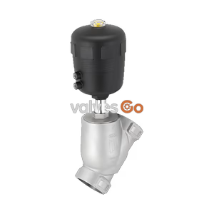
Burkert Type 2961 manually operated 2-way globe control valve. Features exchangeable seats, visual position indicator, and stainless steel body for up to 230°C and 25 bar.
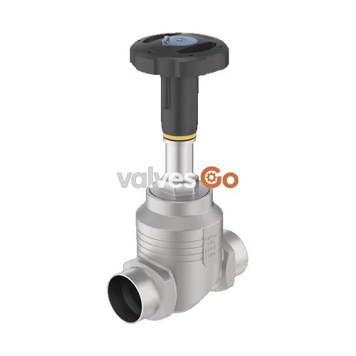
The Burkert Type 2961 control valve consists of a manual actuator and a globe valve body with exchangeable seats made of high-quality stainless steel. Each globe valve body can be equipped with up to 8 valve seat sizes and reaches the desired flow characteristic curve in interaction with parabolic cones. The precise spindle guide enables control, even under demanding operating conditions.
A soft PTFE or PEEK seal guarantees reliable sealing. The actuator is made of high-quality plastic and is suitable for use in demanding environments. It possesses a visual position indicator and can be optionally equipped with stroke limitation and locking. The packing gland uses tried-and-tested V-seals and possesses spring compensation, which means that it does not need to be pulled back manually.

| Property | Value |
|---|---|
| Design | Globe control valve |
| Nominal diameter | DN 10...DN 100, NPS 3/8...NPS 4 |
| Flow direction | Flow to open (below seat) |
| Operating pressure | 0 bar(g)...25 bar(g) |
| Nominal pressure | PN 25 (DIN EN 1333), Class 150 (DIN EN 1759) |
| Seat leakage | Leakage class II (metal), Leakage class VI for PTFE and PEEK (DIN EN 60534-4) |
| Kv value | 0.1 m³/h...140 m³/h |
| Operating characteristic | Equal percentage (50:1 theoretical rangeability) |
| Medium temperature | -40 °C...+ 230 °C |
| Ambient temperature | -10 °C...+ 60 °C |
| Viscosity | Max. 600 mm²/s |
| Element | Material |
|---|---|
| Cover | Polyamide (PA) |
| Handwheel | Polyphenylene sulphide (PPS) |
| Visual position indicator | Polyamide (PA) |
| Packing gland | PTFE V-rings (filled), with spring compensation |
| Stem | Stainless steel 1.4401 or 1.4404 |
| Control cone | 1.4571 (optionally hardened) |
| Seat seal (optional) | PTFE or PEEK |
| Valve body | Stainless steel 316L/CF3M |
| Tight sealing required | Leakage class | Medium temperature | Seat seal |
|---|---|---|---|
| No | II (metal seals) | -40 °C...+230 °C | Stainless steel |
| Yes | VI (soft seals) | -40 °C...+130 °C (recommended for ≤ +130 °C) | PTFE |
| Yes | VI (soft seals) | -10 °C...+230 °C (recommended for > +130 °C) | PEEK |
Optional Variants
Derating as per DIN EN 12516-1/PN25:
| Temperature [°C] | Operating pressure [bar] |
|---|---|
| -10...+50 | 25 |
| 100 | 24.5 |
| 150 | 22.4 |
| 200 | 20.3 |
| 230 | 19 |
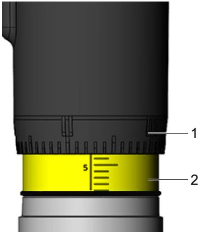
When turning the handwheel anticlockwise, the reproducible stroke scale becomes visible between the position indicator and the handwheel.
Note
The scale on the handwheel determines the rotation position of the handwheel (50 positions). The reproducible stroke scale shows, depending on the bottom edge of the handwheel, the relative position of the valve (valve opening) and acts as a fixation point for determining the rotation position.
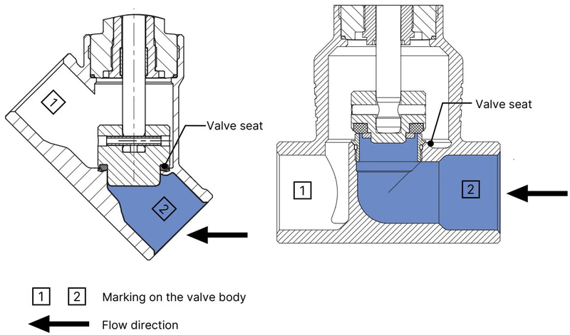
The valve seat is always closed against the medium flow. The flow direction should therefore be set such that the valve reaches the flow beneath the valve seat.

Safety Instructions
Setting the minimum and maximum stroke limit is possible as an option using an adjusting sleeve.
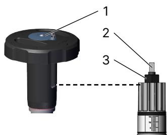
It is also an option to lock the handwheel to prevent unintentional or unauthorised operation of the valve. The locking pin has a bore (Ø 3.8) and can be secured against unauthorised use with a padlock.
Explosion Hazard due to Electrostatic Charge
If a statically charged device or person suddenly discharges, there is a risk of explosion in potentially explosive areas.
For media with varying conductivities, specific flow rate limits and grounding procedures must be strictly followed according to IEC 60079-32-1 to prevent electrostatic hazards.
Explore similar products in our catalog