
Dry Steam Discharge

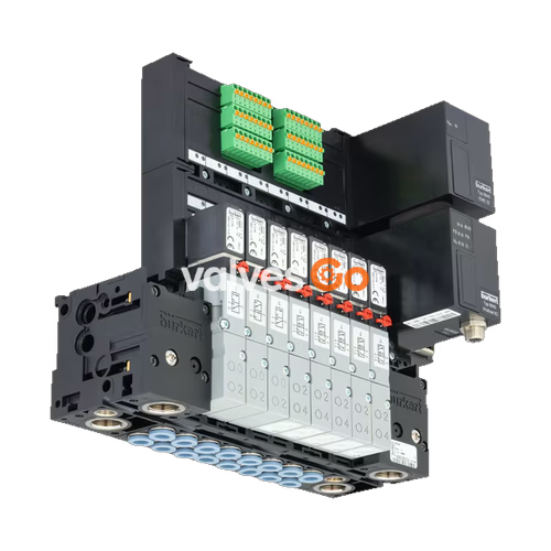
BURKERT 20084095 Type 8640 is a modular valve island designed to solve diverse and complex control problems due to its systematic modular construction and combination of pneumatic and electrical interfaces. By putting together a row of pneumatic modules with different numbers of valves, multiple valve functionalities may be realized on one valve unit. This specific 12-bank configuration features a 33mm add-on dimension, G 1/2 pressure ports, and operates within a 2 to 8 bar pressure range.
Bodies and connection modules are made of high-quality plastic (polyamide) and are easy to assemble by means of built-in snap connectors. The system allows for higher flexibility in the control cabinet due to AirLINE Quick compatibility and enables the simple exchange of valves.

| Feature | Specification |
|---|---|
| Model | 20084095 (Type 8640) |
| Configuration | 12-bank, 33 mm add-on dimension |
| Pressure Port (1) | G 1/2 |
| Working Port (2, 4) | G 1/4 (opposite of supply side) |
| Nominal Pressure | 2 bar to 8 bar |
| Medium Temperature | 0 °C to +50 °C |
| Ambient Temperature | 0 °C to +55 °C |
| Mounting Type | DIN-rail installation |
| Protection Type | IP20 (max. with suitable connector) |
| Operating Medium | Oil-free or lubricated compressed dry air, neutral gases (5 μm filter recommended) |
Compatible Pilot Valves
The Type 8640 modular valve island can be combined with various pilot valves depending on the application requirements, including Type 6524, Type 6525, Type 0460, Type 6526, Type 6527, and Type 5470.
WARNING
Risk of injury due to high pressure and escaping medium. Switch off the pressure before working on the device or system. Vent or drain the pipes.
Risk of injury due to electric shock. Switch off voltage before working on the device or system. Secure against reactivation.
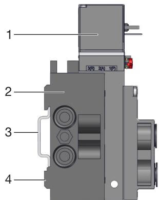
Standard rail installation:
Wall installation: Fasten the valve block directly to the wall with M4 screws.
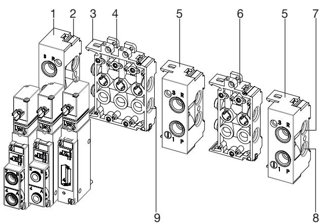
WARNING
Crushed O-rings and profile seals lead to leaky blocks. Fasten each valve to the base module with 2 screws. Recommended tightening torque 0.6 ±0.1 Nm.
Push the hose lines into the push-in connections of the solenoid valves until they come to a stop. Use PTFE tape or elastomer seal for sealing the threaded connection.
Recommended action for push-in connectors
| Fault | Possible Cause | Remedy |
|---|---|---|
| Valves do not switch | No operating voltage or operating voltage too low | Check electrical connection. Ensure operating voltage according to type label. |
| Manual override not in zero position | Bring manual override to zero position. | |
| Pressure supply insufficient or not available | Set up large-volume pressure supply. Minimum operating pressure ≥ 2 bar. | |
| Valves switch with a delay or blow off at the exhaust ports | Valves are not in the home position (de-energised) during pressure build-up | Apply pressure to the valve block before the valves are switched. |
| Insufficient ventilation of the exhaust air ducts due to too small or dirty silencers | Use suitably sized silencers or expansion vessels. Clean the dirty silencers. | |
| Leaky valve blocks | Missing or crushed O-rings between the modules | Identify leak or missing seals. |
| Missing or incorrectly positioned flat seals between valve and base plate | Insert missing seals or replace damaged seals. |