3450 RPM Motors

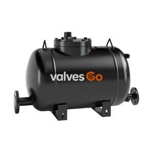
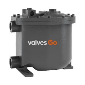
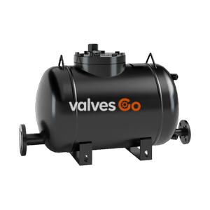
Armstrong PT-516 non-electric high capacity pump trap for condensate recovery. Max capacity 80,000 lb/hr, max operating pressure 150 psig. Ideal for low pressure heating and vacuum systems.
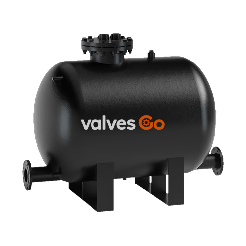
Armstrong PT-516 High Capacity Pump Trap is the low maintenance, non-electric solution to moving large amounts of condensate and other liquids from low points, low pressures, or vacuum spaces to an area of higher elevation or pressure. Condensate can be returned at temperatures well above the 200°F (93°C) limit of conventional electric pumps without the headaches of leaking seals or cavitation. Effective recovery and return of hot condensate are essential to overall plant efficiency while conserving energy.
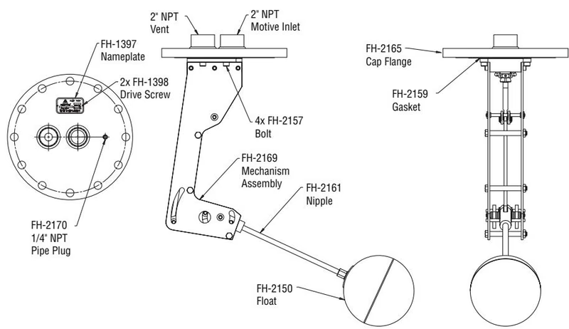
| Name of Part | Description |
|---|---|
| Cap, Body, Bolting | Fabricated steel 150 psi ASME Sec. VIII design “U” stamp coded |
| Cap Gasket | Stainless steel spiral wound |
| Inlet Valve Assembly | Stainless steel |
| Vent Valve Assembly | Stainless steel |
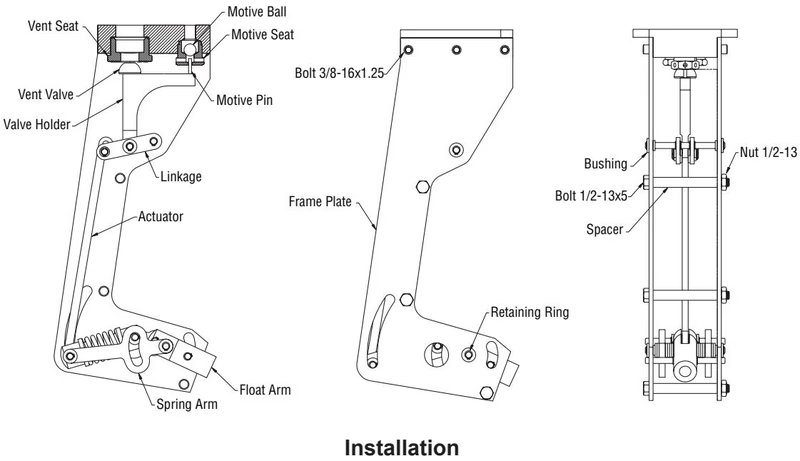
| Mechanism Assembly: Frame, Float and Spring | Stainless steel (Inconel X-750 springs) |
Published capacities below are based on actual steam testing using a minimum 200°F condensate and the use of external check valves supplied by Armstrong.
| Motive Pressure (psig) | Total Lift or Back Pressure (psig) | Steam Motive (lb/hr) | Air Motive (lb/hr) |
|---|---|---|---|
| 15 | 5 | 28,962 | 57,619 |
| 35 | 5 | 42,563 | 64,738 |
| 75 | 5 | 54,796 | 71,142 |
| 150 | 5 | 65,922 | * |
| 25 | 15 | 36,720 | 50,783 |
| 50 | 15 | 45,196 | 58,013 |
| 100 | 15 | 55,675 | 65,243 |
| 150 | 15 | 62,923 | * |
| 35 | 25 | 29,212 | 46,238 |
| 75 | 25 | 38,548 | 56,313 |
| 100 | 25 | 42,454 | 60,141 |
| 50 | 40 | 26,210 | 41,244 |
| 100 | 40 | 30,555 | 51,828 |
| 150 | 40 | 33,097 | * |
| 70 | 60 | 25,973 | 32,026 |
| 100 | 60 | 28,042 | 40,951 |
| 150 | 60 | 30,394 | * |
| 100 | 80 | 23,892 | 34,893 |
| 150 | 80 | 24,570 | * |
*(Note: Capacities shown are for 4" x 4" connections with a 24" fill head. Consult factory for values marked with )
Motive Pressure Recommendation
Although the maximum operating pressure is 150 psig (10.34 bar), it is recommended that the motive pressure be set to 30 psig (2.07 bar) above the back pressure. This will provide optimum performance and reduce venting time between cycles.
Filling Head: Install the PT-516 below the equipment being drained. A minimum filling head of 24" is required for the PT-516. Filling head is measured from the bottom of the receiver or reservoir pipe to the top of the PT-516 cap.
Check Valves: The PT-516 will not function without inlet and discharge check valves. Connect the Armstrong supplied check valves to the pump. The PT-516 has two (2) 4" flanged connections. Best performance is achieved when a minimum of horizontal pipe is used before the inlet check valve.
Motive Inlet Piping: Connect the motive force piping (steam, air, or gas) to the inlet connection on the PT-516 cap. Proper piping and trapping of the motive supply line must include a strainer, check valve, properly sized drip leg with mud pocket and drip trap. The motive supply line must be a minimum of 2".
Vent Connection: Piping from the pump’s cap connection should be installed vertically upward when possible and unrestricted. The minimum size of this vent piping should be 2". If piping travels longer than 10 feet, the piping should be expanded to a minimum of 3".
Cycle Counter Installation: There is a 1/4" connection on top of the cap where the cycle counter can be mounted. One (1) 1/4" pigtail siphon and 1/4" isolation valve are required. It is very important that a steel siphon or “pig tail” be used prior to the cycle counter to avoid any damage to the cycle counter.
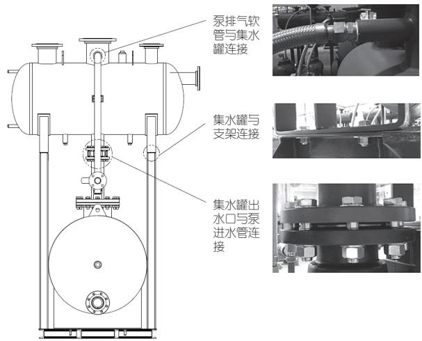
Packaged Connections: A pumping trap receiver package designates the number of pumps with an “S” for single (one pump), “D” for duplex (two pumps), “T” for triple (three pumps) and “Q” for quad (four pumps). For example: SPT-516RP or DPT-516RP. All receiver tanks should be operated at atmospheric pressure (vented) unless the package was ordered with an ASME coded tank.
Safety Warning
For Safety of Personnel - Vent line piping should be isolated from equipment and pump pressure should be relieved prior to breaking connections. WATER MAY RUN OUT OF THE VENT CONNECTION WHEN PIPING IS BROKEN. CARE SHOULD BE TAKEN TO AVOID DANGER TO PERSONNEL OR DAMAGE TO NEARBY EQUIPMENT.
Explore similar products in our catalog