


PN25

The Armstrong GD-24 is a lightweight, compact, and economical bronze pressure reducing valve for non-potable hot or cold water systems. Features NPT connections and ANSI Class IV shutoff.
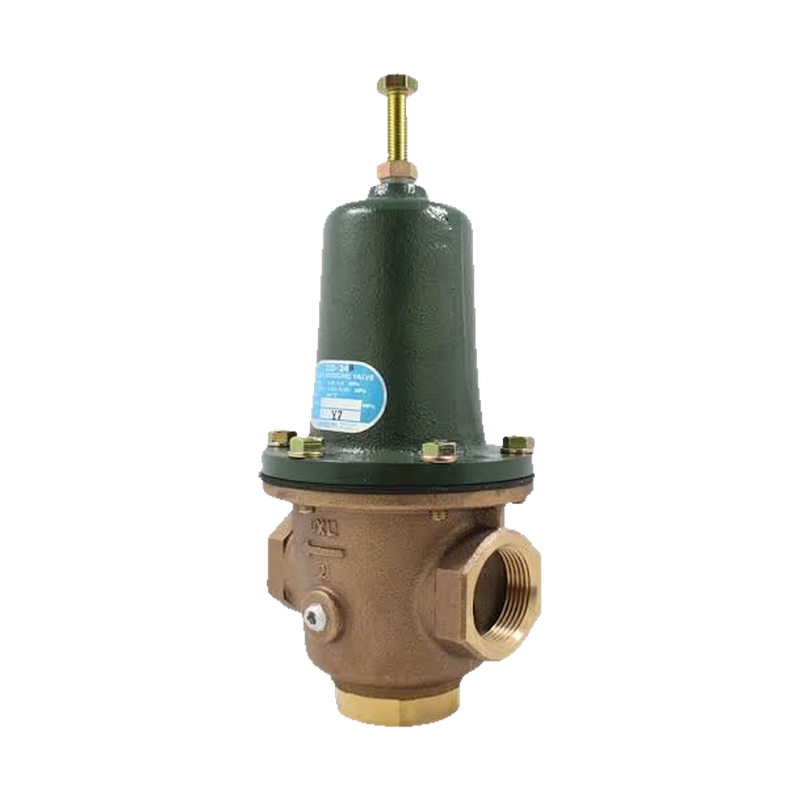
Armstrong GD-24 is an industrial-grade pressure reducing valve for non-potable water systems. It is lightweight, compact, and economical. The valve comes with screwed connections and will mount in any position, requiring no external sensing lines. Its bronze body and high-temperature diaphragm are suitable for hot or cold process water service. The valve, seat, and diaphragm are renewable in line. It features an external adjusting screw with a lock and provides ANSI Class IV shutoff.
WARNING
Illegal for potable water service per SDWA section 1417 (As Amended). For Non-Potable Water Service Only.
| Application | Maximum Pressure psig (bar) | Reduced Pressure Range psig (bar) | Minimum Differential psig (bar) | Maximum Temperature °F (°C) | Body Material | Main Valve | Valve Seat | Diaphragm |
|---|---|---|---|---|---|---|---|---|
| Hot or Cold Water | 230 (16) | 7 - 80 (0.48 - 5.5) | 7 (0.48) | 175 (79)* | Cast Bronze ASTM 584 | Stainless Steel AISI 304 | Stainless Steel AISI 304 | NBR** |
*With Viton® diaphragm maximum temperature is 210°F (99°C).**Viton optional.
| ΔP (psig) | 1/2" | 3/4" | 1" | 1-1/4" | 1-1/2" | 2" | ΔP (bar) | 15mm | 20mm | 25mm | 32mm | 40mm |
|---|---|---|---|---|---|---|---|---|---|---|---|---|
| 7 | 4 | 5 | 8 | 11 | 19 | 26 | 0.5 | 15 | 20 | 30 | 40 | 70 |
| 10 | 5 | 6 | 9 | 13 | 22 | 32 | 0.7 | 18 | 24 | 36 | 48 | 84 |
| 15 | 6 | 8 | 12 | 15 | 27 | 39 | 1.0 | 22 | 29 | 44 | 59 | 103 |
| 25 | 8* | 10 | 15 | 20 | 35 | 50 | 1.7 | 30* | 38 | 57 | 76 | 132 |
| 50 | 11 | 14* | 21 | 28 | 49 | 71 | 3.4 | 40 | 53* | 80 | 107 | 187 |
| 75 | 13 | 17 | 26* | 35 | 61* | 87 | 5.2 | 49 | 66 | 98* | 131 | 231* |
| 100 | 15 | 20 | 30 | 40* | 70 | 100* | 6.9 | 57 | 76 | 114 | 151* | 265 |
| 125 | 17 | 22 | 34 | 45 | 78 | 112 | 8.6 | 63 | 85 | 127 | 169 | 296 |
| 150 | 18 | 24 | 37 | 49 | 86 | 122 | 10.3 | 70 | 93 | 139 | 185 | 325 |
| 175 | 20 | 26 | 40 | 53 | 93 | 132 | 12.0 | 75 | 100 | 150 | 200 | 351 |
| 200 | 21 | 28 | 42 | 57 | 99 | 141 | 13.8 | 80 | 107 | 161 | 214 | 375 |
INFO
*At flows greater than this, velocities will exceed 10 ft/sec and pipe erosion could occur. NOTE: Maximum pressure reduction ratio 10:1.
| Size | 1/2" (15mm) | 3/4" (20mm) | 1" (25mm) | 1-1/4" (32mm) | 1-1/2" (40mm) | 2" (50mm) |
|---|---|---|---|---|---|---|
| L | 3-1/4" (83mm) | 3-1/2" (89mm) | 4" (102mm) | 4-3/4" (121mm) | 6" (152mm) | 7-1/4" (184mm) |
| H1 | 1-3/4" (45mm) | 2" (51mm) | 2-1/2" (64mm) | 3-1/4" (83mm) | 3-1/2" (89mm) | 4-1/2" (115mm) |
| H | 7-3/4" (197mm) | 8-1/2" (216mm) | 9-5/8" (245mm) | 11-1/4" (286mm) | 13-1/2" (343mm) | 16" (407mm) |
| Weight | 4 lb (1.8 kg) | 5-1/4 lb (2.4 kg) | 7-1/4 lb (3.3 kg) | 10-3/8 lb (4.7 kg) | 18 lb (8.2 kg) | 31-1/2 lb (14.3 kg) |
| Cv | 1.5 | 2 | 3 | 4 | 7 | 10 |
WARNING
Improper adjustment of the pressure reducing valve may cause hunting, improper control, and possible damage to the valve itself. Adjust the valve as follows:
| Problem | Causes | Solutions |
|---|---|---|
| The intended pressure cannot be obtained. | Inlet pressure is too low or too high. | Adjust the pressure to the appropriate level. |
| The inlet strainer is clogged. | Disassemble and clean the strainer. | |
| The adjustment is not appropriate. | Readjust the valve according to the adjusting procedure. | |
| The pressure gauge is out of order. | Replace the pressure gauge. | |
| The valve size is smaller than what is required. | Replace the valve with a suitable size valve. | |
| The reduced pressure is higher than the specified level. | The valve and valve seat are contaminated by a foreign substance. | Disassemble and clean the valve body and the valve seat. |
| The bypass valve is leaking. | Repair or replace the bypass valve. | |
| The diaphragm is ruptured. | Replace the diaphragm. | |
| Abnormal noise is heard. | Excessive air is in the system. | Install an air vent. |
| The valve size is larger than what is required. | Install the correct size valve. | |
| A quick operating valve is installed near the pressure reducing valve (i.e. solenoid valve). | Provide as much distance as possible between the two valves. |
The GD-24 PRV is composed of two components: body and spring chamber.
Notes to Reassembly
Reassemble in the reverse order of disassembly.
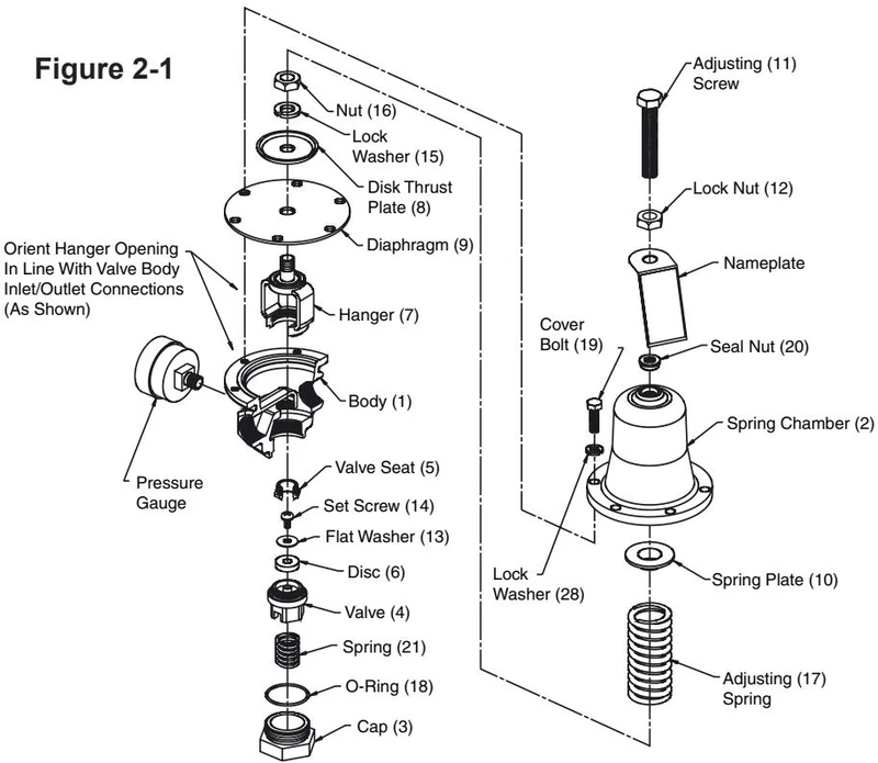 Orient Hanger Opening In Line With Valve Body Inlet/Outlet Connections (As Shown)
Explore similar products in our catalog



